FINAL PROJECT
Robotic Arm System for Object Sorting
The increasing demand for automation in industrial environments necessitates innovative solutions for efficient sorting processes. This project proposes the design and development of an advanced 6-axis servo robotic arm system integrated with a camera and a controller to address the industrial challenge of sorting objects by size and color into designated bins.
System Overview
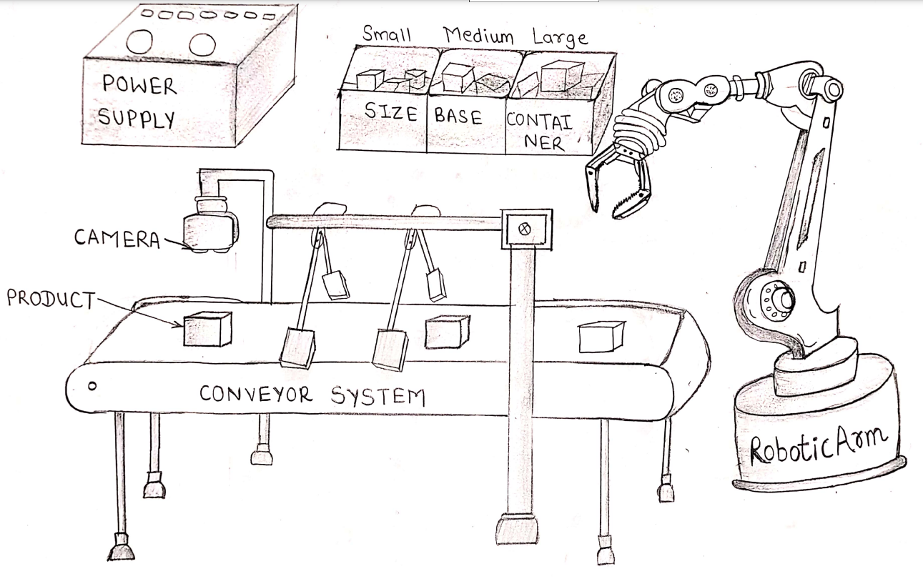
The proposed system consists of a conveyor belt, a camera, a controller, a robotic arm with servo motors, and a defaulter mechanism. The workflow is as follows:
1. A camera positioned above the conveyor belt continuously monitors objects in motion.
2. The computer vision system identifies the size and color of each object.
3. The controller processes this data in real-time and generates commands for the robotic arm.
4. The 6-axis servo robotic arm picks up identified objects and places them in designated bins.
5. Faulty or unidentifiable objects are sorted separately by the defaulter mechanism.
6. The dual operation of the robotic arm and defaulter ensures seamless sorting without congestion.
Objectives
• To develop an automated sorting system using a 6-axis servo robotic arm.
• To integrate a computer vision-based camera system for real-time object detection.
• To implement a controller for processing data and executing robotic commands.
• To incorporate a defaulter mechanism for managing unidentifiable or faulty objects.
• To optimize sorting efficiency and minimize processing delays.
Key Features
• High-Precision Sorting: The 6-axis servo robotic arm ensures accurate placement of objects.
• Real-Time Processing: The integration of computer vision allows instant data analysis and decision-making.
• Defaulter Mechanism: Manages faulty objects to maintain an uninterrupted workflow.
• Industrial-Grade Performance: Designed for speed, precision, and reliability in manufacturing environments.
Expected Outcomes
• Improved sorting accuracy for industrial applications.
• Enhanced efficiency in object classification and placement.
• Reduced manual labor and increased automation.
• A scalable solution adaptable to different industries and sorting requirements.
Conclusion
By integrating robotics, computer vision, and real-time control, this project presents a cutting-edge solution for industrial sorting challenges. The combination of a high-precision robotic arm and an intelligent sorting mechanism enhances workflow efficiency and reliability, making it a valuable addition to modern manufacturing and automation systems.
3d modeling of Robotic Arm
Since this robotic arm is a major component of my final project, its design and manufacturing using 3D printing were completed during this week.
I used SolidWorks 3D software to design the part. Using this software, I first designed the base component.
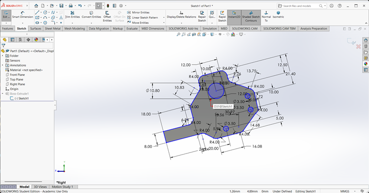
1. Base
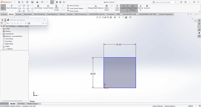
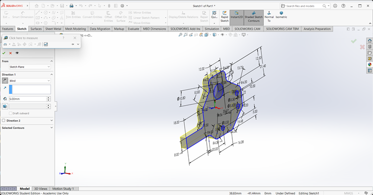
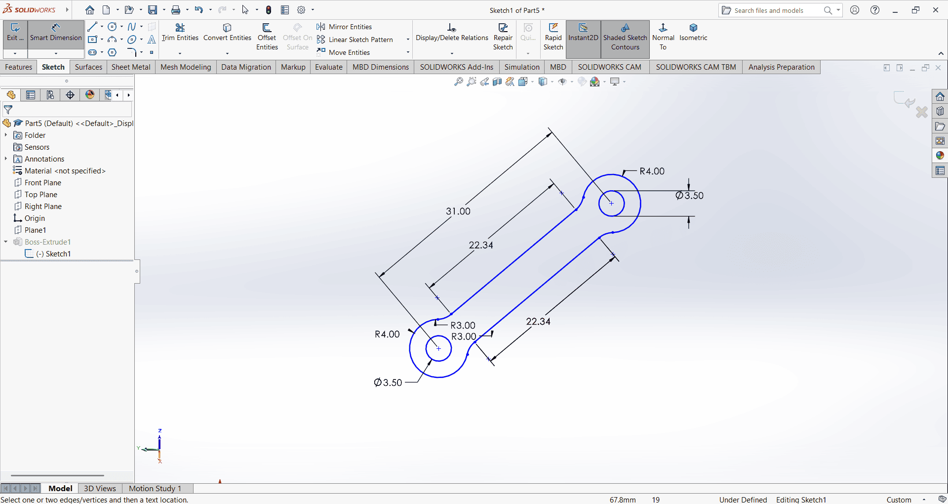
When starting the base design, I first created an accurate 2D sketch using various commands such as Circle, Trim, Line, and Rectangle.
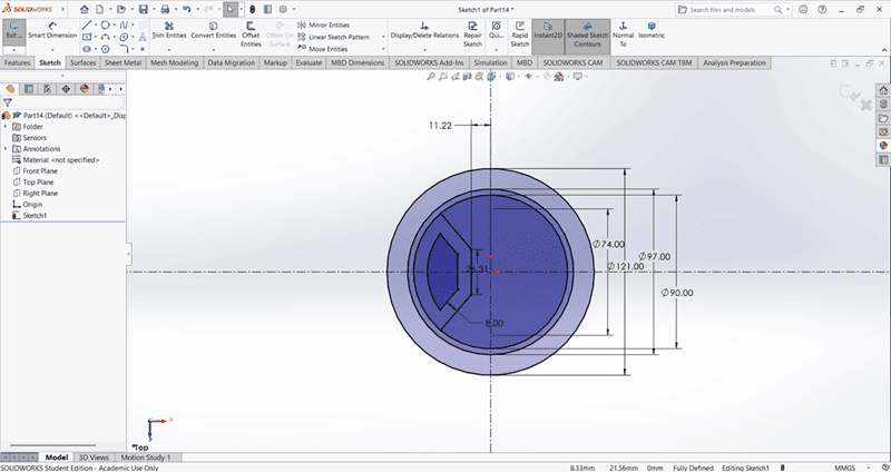
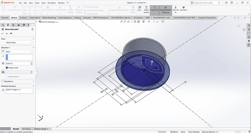
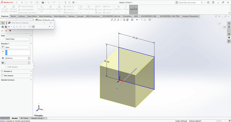
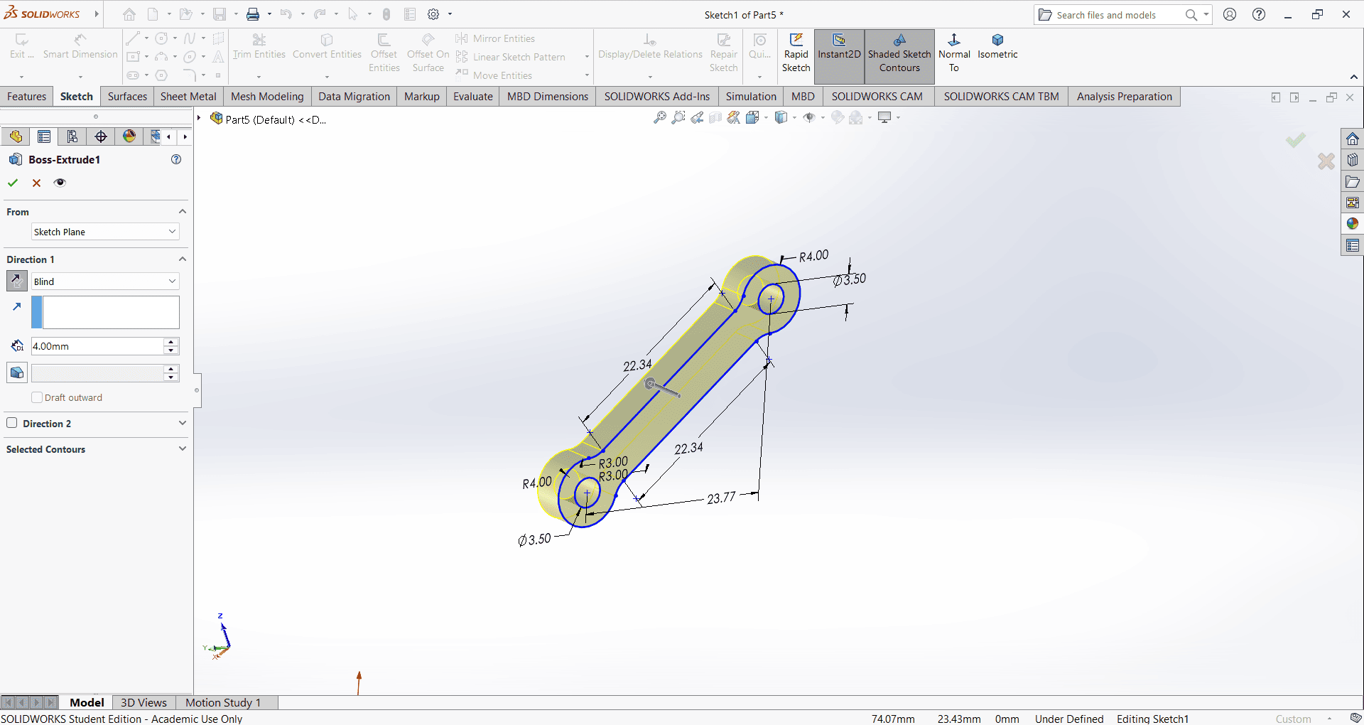
Then, I used the Extrude Boss/Base command to extend the part to the desired height
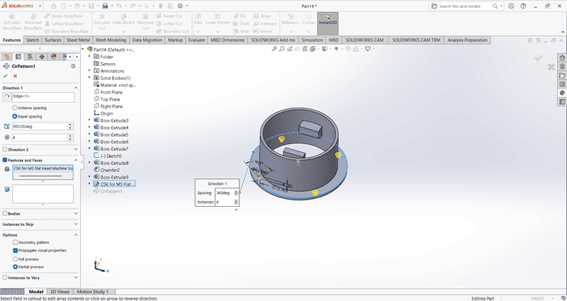
Using the Circular Pattern command, create four evenly spaced small holes along the periphery of the base.
Use the Cut Extrude command to create a circular hole in the base
2. Arm 1
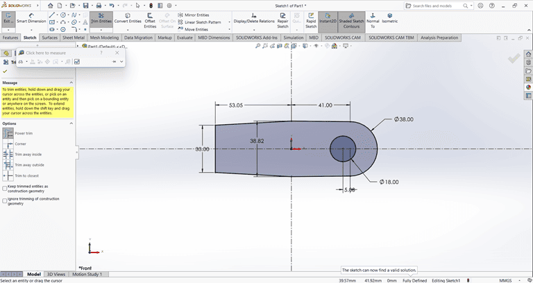
When starting the arm 1 design, I first created an accurate 2D sketch using various commands such as Circle, Trim, Line, and Rectangle.
Then, I used the Extrude Boss/Base command to extend the part to the desired height
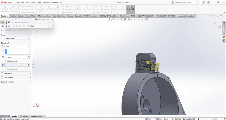
Next, I used the Cut Extrude command to create a circular hole in the arm at the desired depth.
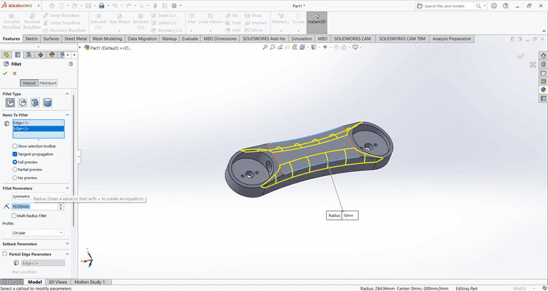
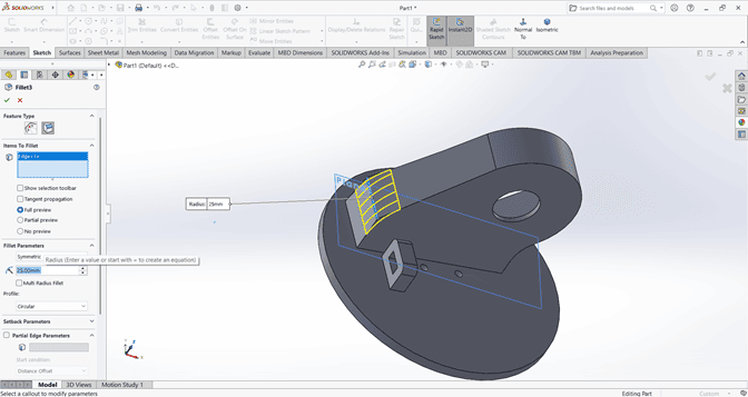
Then, use the Fillet command to round the edges of the rectangular shape, applying a fillet radius of 10 mm.
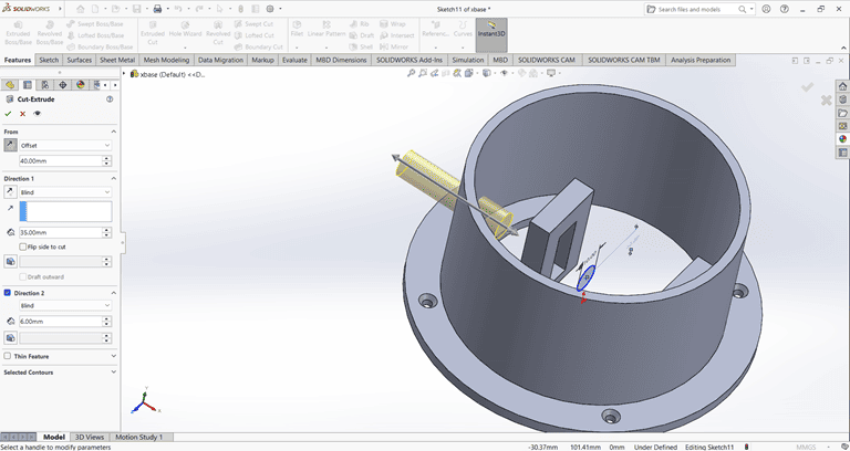
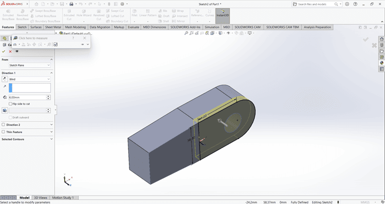
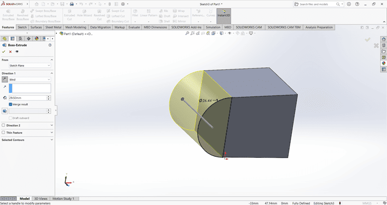
Next, create a small feature on the outer side of the arm and extrude it using the Midplane option. Then, use the Cut Extrude and Boss-Base commands to achieve the required shape.
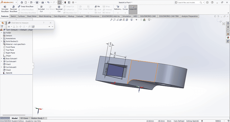
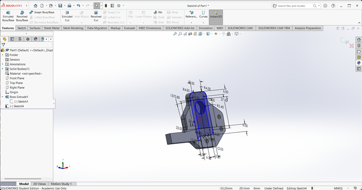
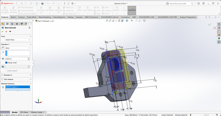
2. Arm 2
When starting the arm 2 design, I first created an accurate 2D sketch using various commands such as Circle, Trim, Line, and Rectangle.
Then, I used the Extrude Boss/Base command to extend the part to the desired height
Next, I created a rectangle of the required dimensions on the side face. Then, I used the Cut Extrude command to create a rectangular hole through the shape.
Next, I created a circle of the required dimensions on the side face. Then, I used the Cut Extrude command to create a circular hole with the specified dimensions in the shape.
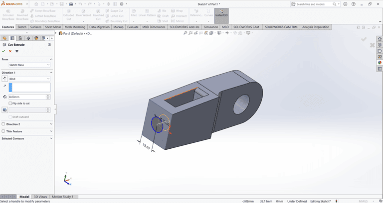
Next, I created the desired shape as shown in the figure. Then, I used the Cut Extrude command to shape it according to the specified dimensions.
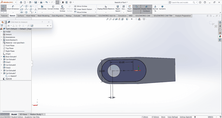
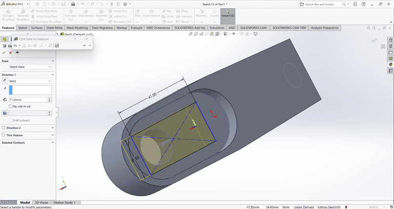
Next, a rectangular shape was created on the same face where the previous Cut Extrude command was applied. Then, the Cut Extrude command was used again to cut through the entire shape.
Finally, the arm part is complete and ready for use.
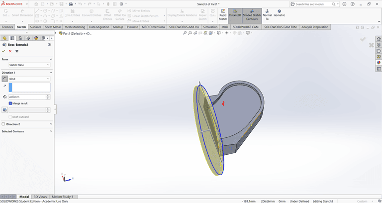
3. Base
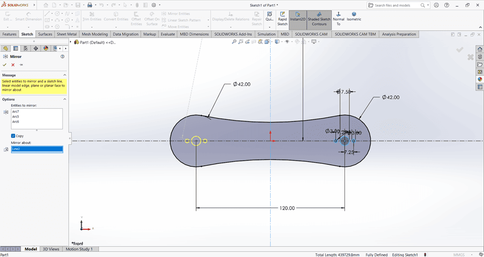
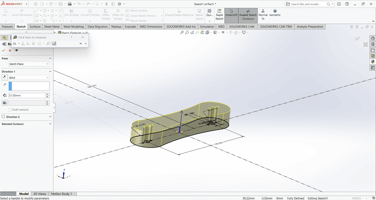
I first created an accurate 2D sketch using various commands such as Circle, Trim, Line, and Rectangle.
Then, I used the Extrude Boss/Base command to extend the part to the desired width.
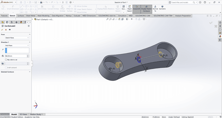
Next, I sketched the required shape on the front face to perform the cut operation.
Next, on the bottom face, I first located the center point and then used the Circle command to draw a circle. After that, I applied the Extrude Boss/Base command to create the base.
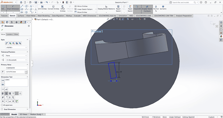
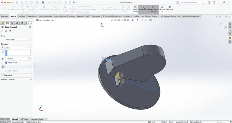
Next, I selected the top face and drew a rectangle at the specified location. Then, I applied the Extrude Boss/Base command. After that, I selected the side face of the rectangle and used the Cut Extrude command to create a rectangular hole.
Next, I applied the Fillet command to the small rectangle with a fillet radius of 3 mm.
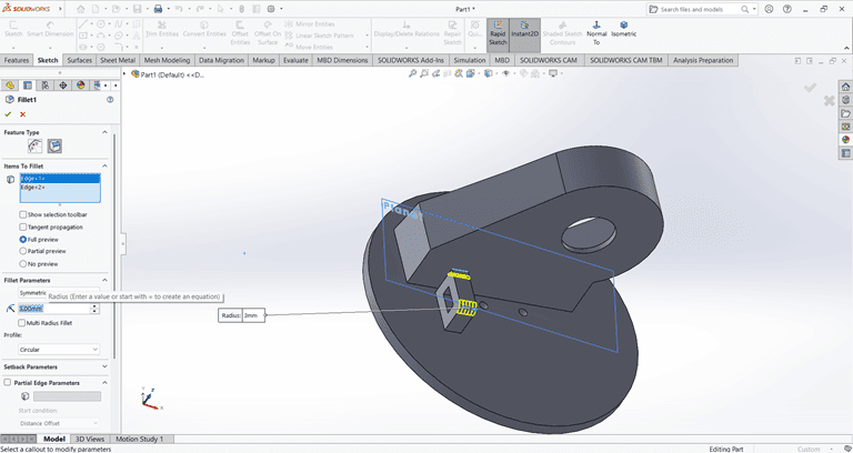
Next, I applied the Fillet command to the main shape with a fillet radius of 20 mm.
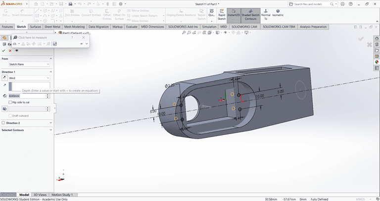
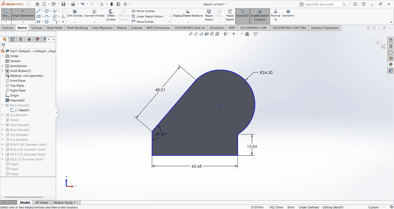
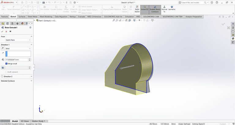
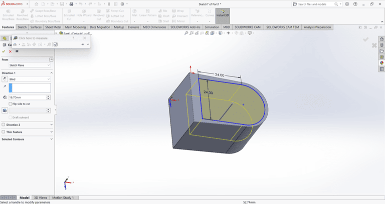
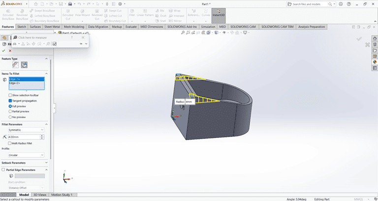
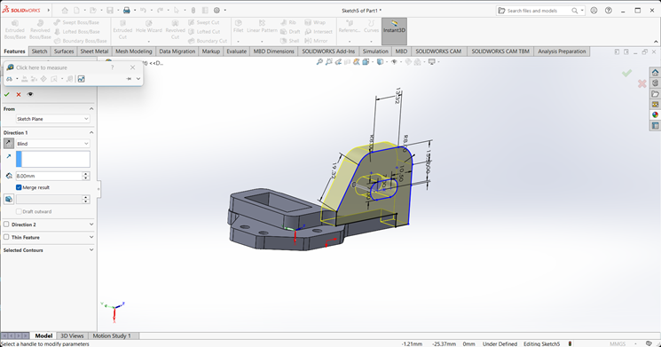
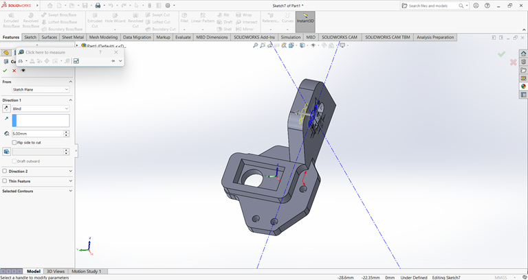
4. Joint
I first created an accurate 2D sketch using various commands such as Circle, Trim, Line, and Rectangle.
Then, I used the Extrude Boss/Base command to extend the part to the desired width.
Next, I created a half-circle on the top of the rectangle.
I created a precise 2D sketch using various commands such as Circle, Trim, Line, and Rectangle.
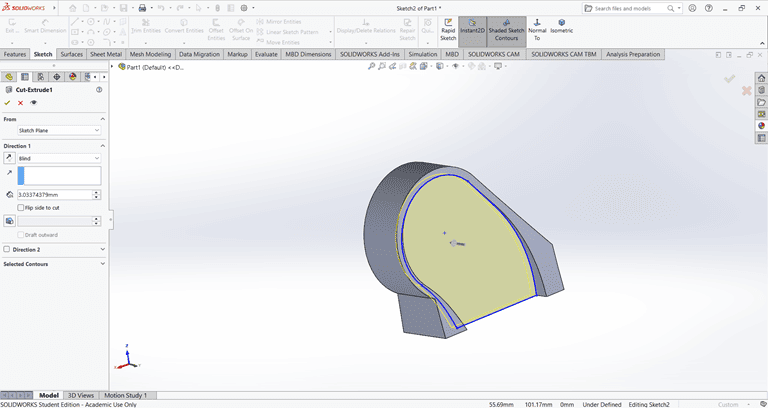
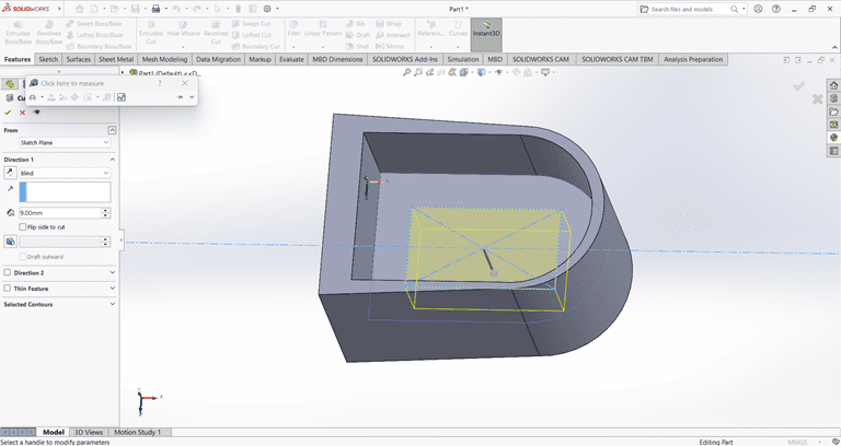
Next, I used the Cut Extrude command to remove that part. Then, on the same face, I sketched a rectangle to be cut in the next step.
Next, on the same face, I used the Circle command to draw a circle with the specified dimensions.
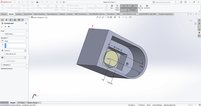
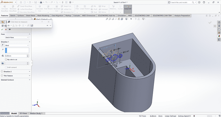
Next, on the bottom side, I used the Circle command to draw a circle with the specified dimensions. Then, I applied the Cut Extrude command to remove that shape.
Next, I drew a triangle on the side face using the Line and Dimension commands. Then, I applied the Cut Extrude command to create a slanted edge.
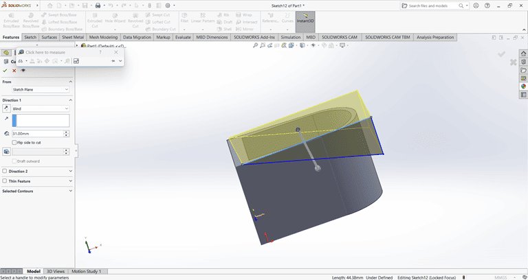
then on that slant edge apply the fillet command of 4mm to edge make circular.
5. Clip
I first created an accurate 2D sketch using various commands such as Circle, Trim, Line, Dimension and Rectangle.
Then, I used the Extrude Boss/Base command to extend the part to the desired width.
Next, on the front face of the extruded part, I created a 2D sketch of the desired shape for extrusion.
I extruded that part upward to the desired height.
On the side face, I created a 2D sketch and extruded it to a width of 8 mm.
Finally, the clip part is complete and ready.
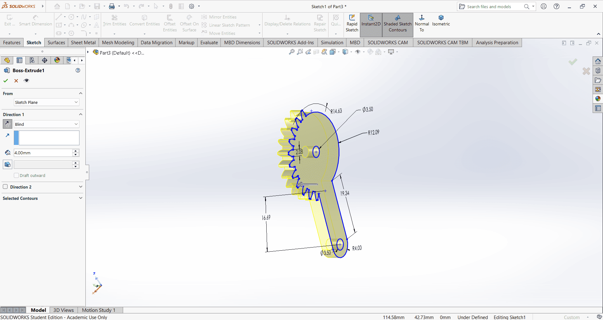
6. Gear
I first created an accurate 2D sketch using various commands such as Circle, Trim, Line, Dimension and Rectangle.
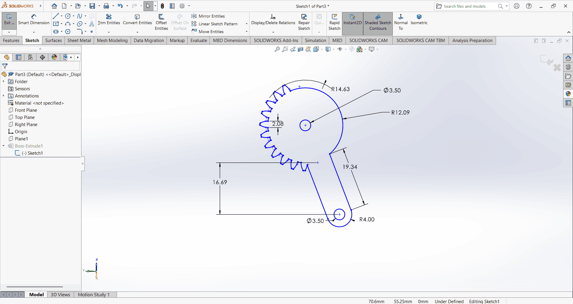
Then, I used the Extrude Boss/Base command to extend the part to the desired height.
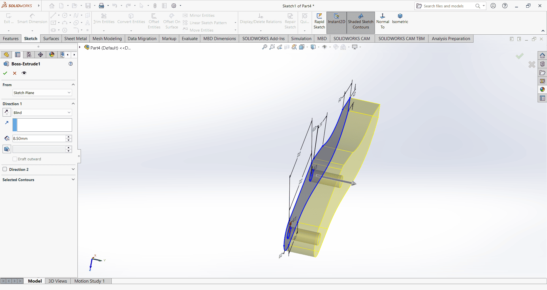
7. Gripper
I first created an accurate 2D sketch using various commands such as Circle, Trim, Line, Dimension and Rectangle.
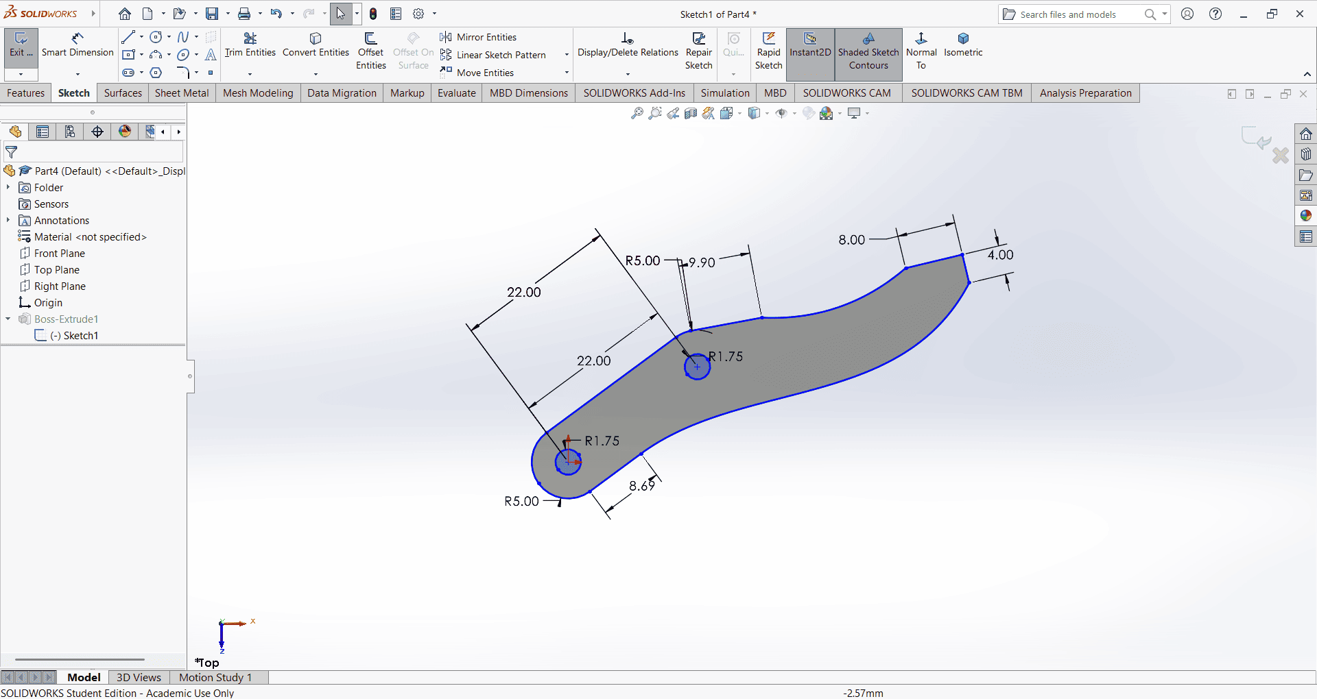
Then, I used the Extrude Boss/Base command to extend the part to the desired height.
8. Pin
I first created an accurate 2D sketch using various commands such as Circle, Trim, Line, Dimension and Rectangle.
Then, I used the Extrude Boss/Base command to extend the part to the desired height.
Slicing
First, I downloaded the STL files in solid works for all parts to generate their G-codes. We then imported all STL file into the Ultimate cura slicing software to generate the G-code required for the 3D printer.
I opened the Ultimaker Cura software and navigated to the File menu. Then, I selected the Import option and chose the previously saved files in STL format.
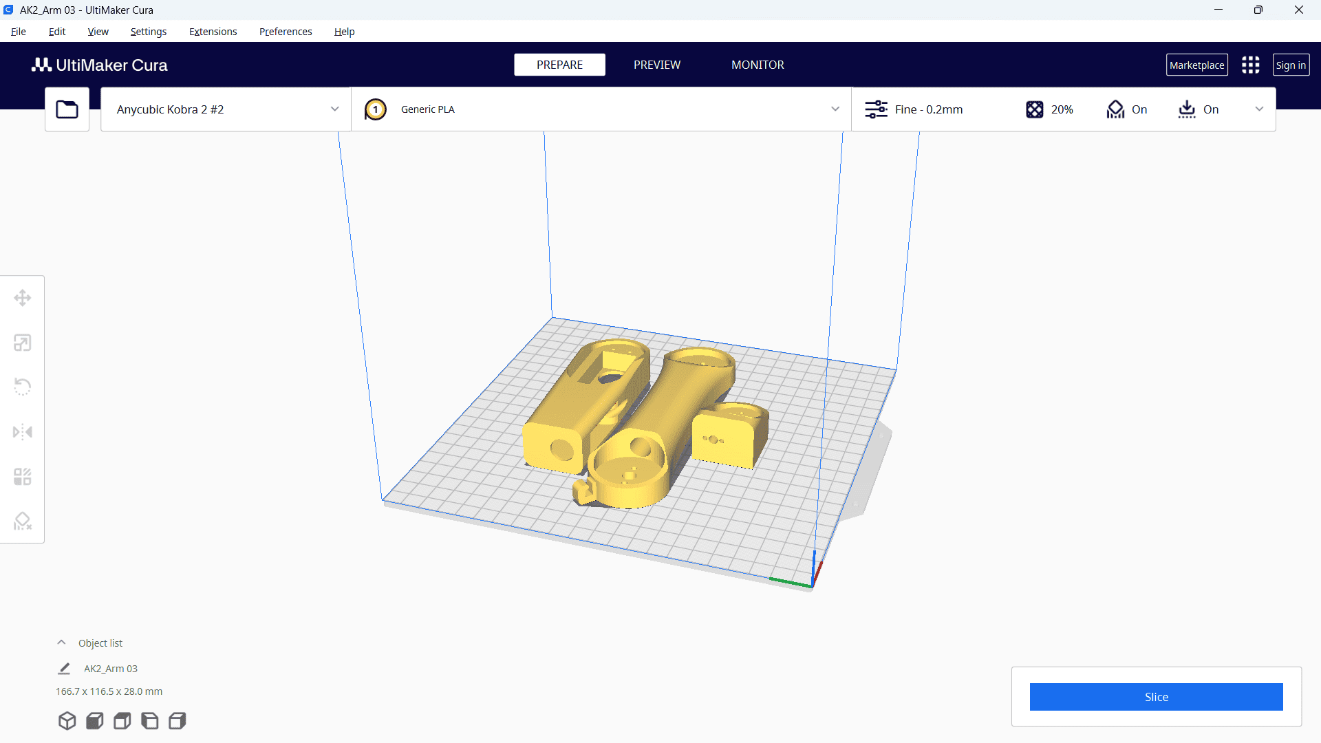
Then, right-click and select "Arrange All Models" to automatically arrange all models in a specific layout. Next, navigate to the print settings and select the "Fine 0.2mm" profile. Set the layer height to 0.2 mm, and configure additional parameters such as infill density, infill pattern, print temperature, build plate temperature, print speed, support structure and material settings as required.
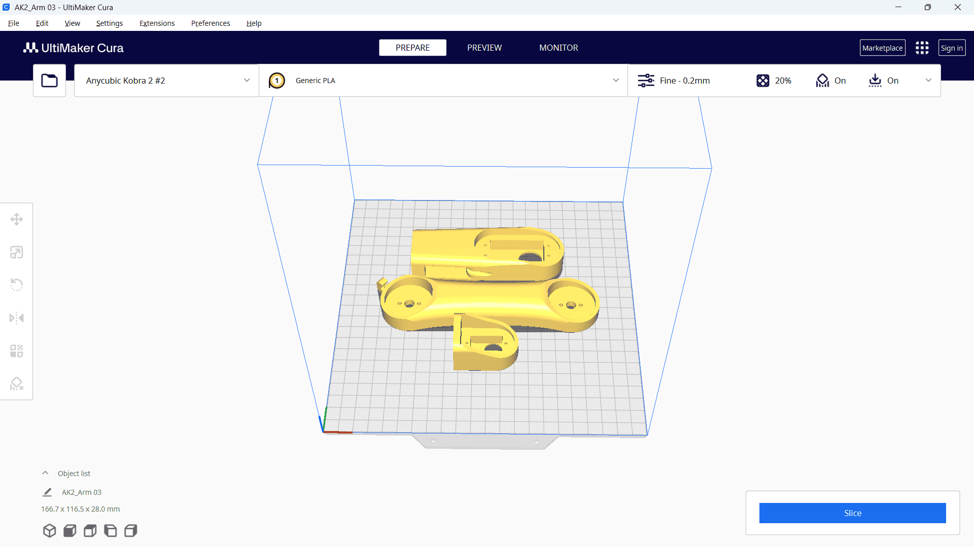
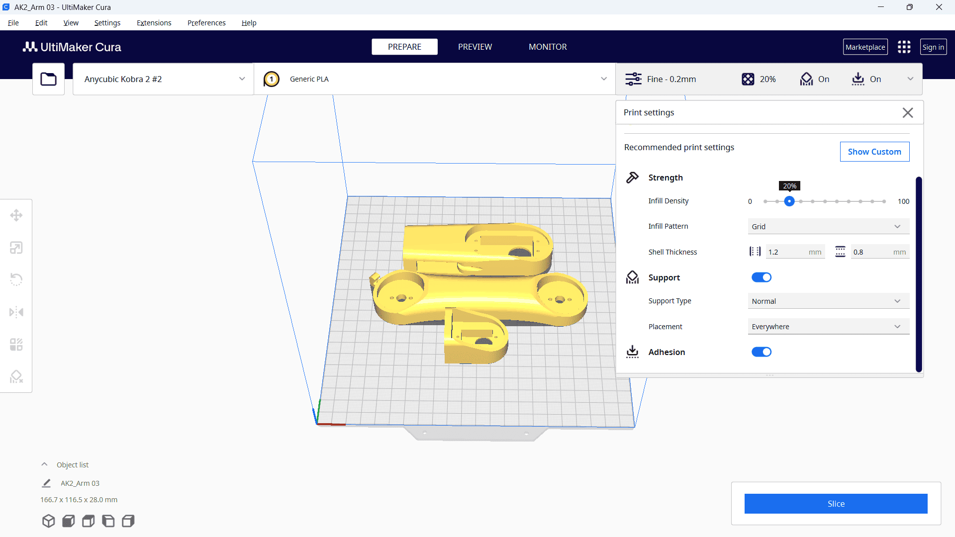
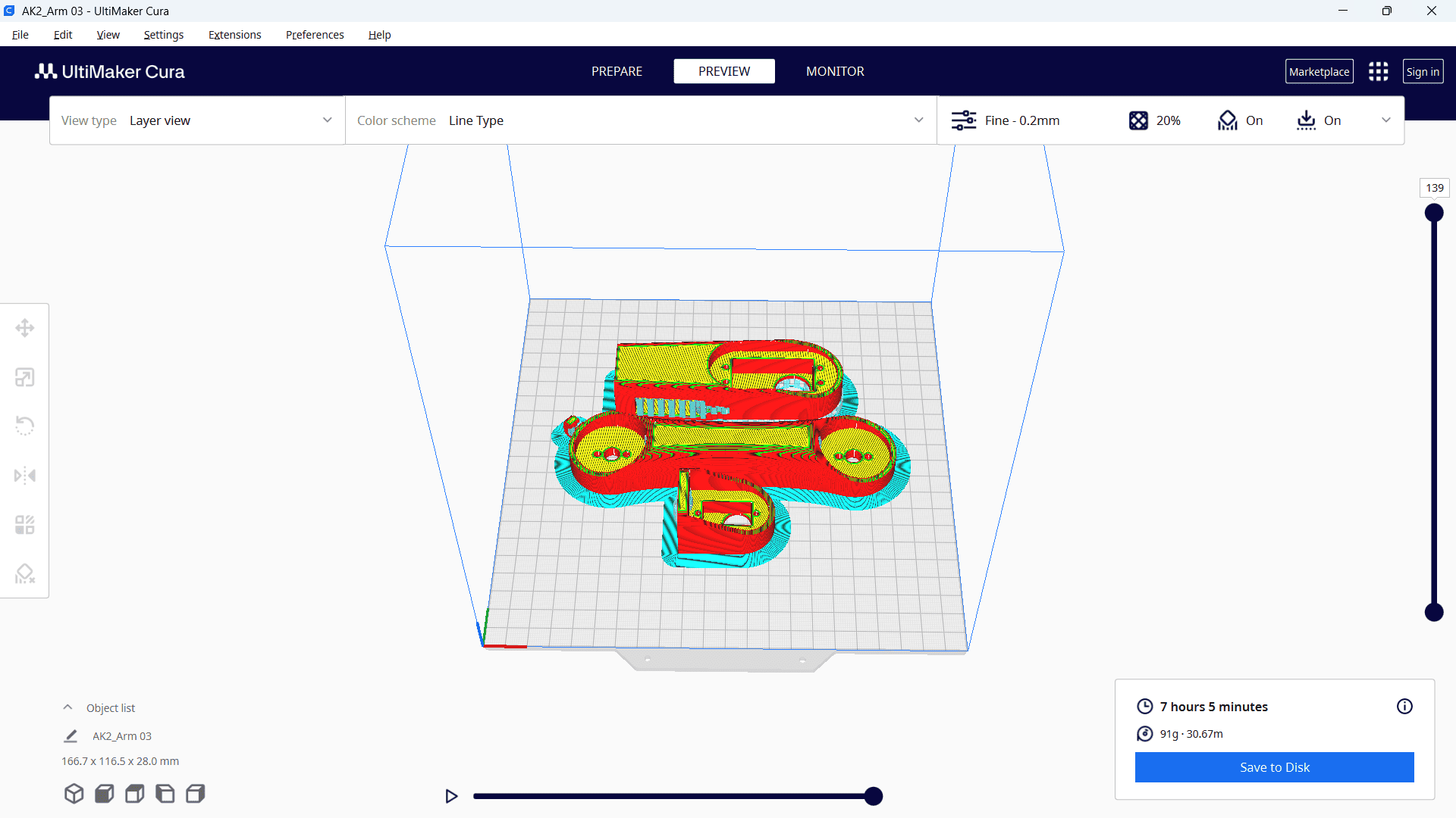
After selecting all the parameters, click "Slice." Once the processing is complete, the required printing time will be displayed.
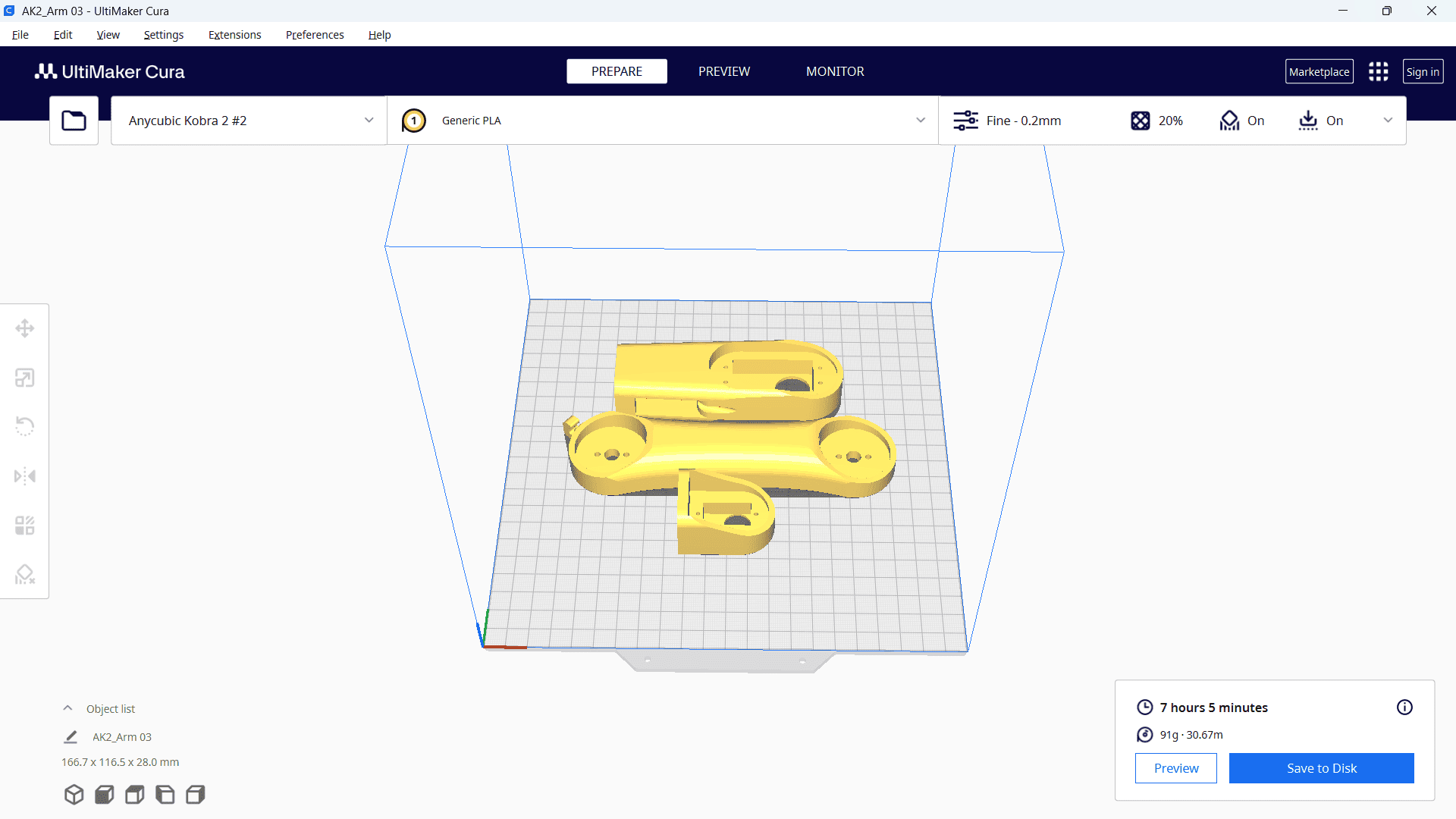
Finally, save the file to a memory card.
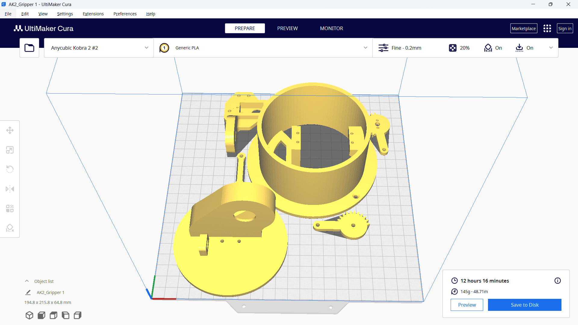
The same process was repeated for the remaining parts, which required 12 hours and 16 minutes for printing.
Printing
After setting up our 3D printer with Nozzle temperature as 210 deg C and bed temperature as 60 deg C.
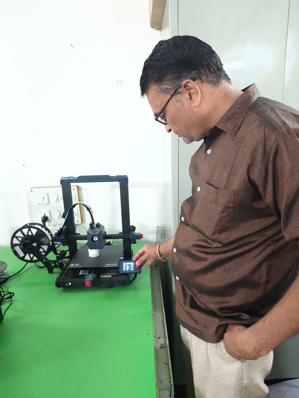
Next, I selected the file from the memory card inserted into the machine and started the printing process.
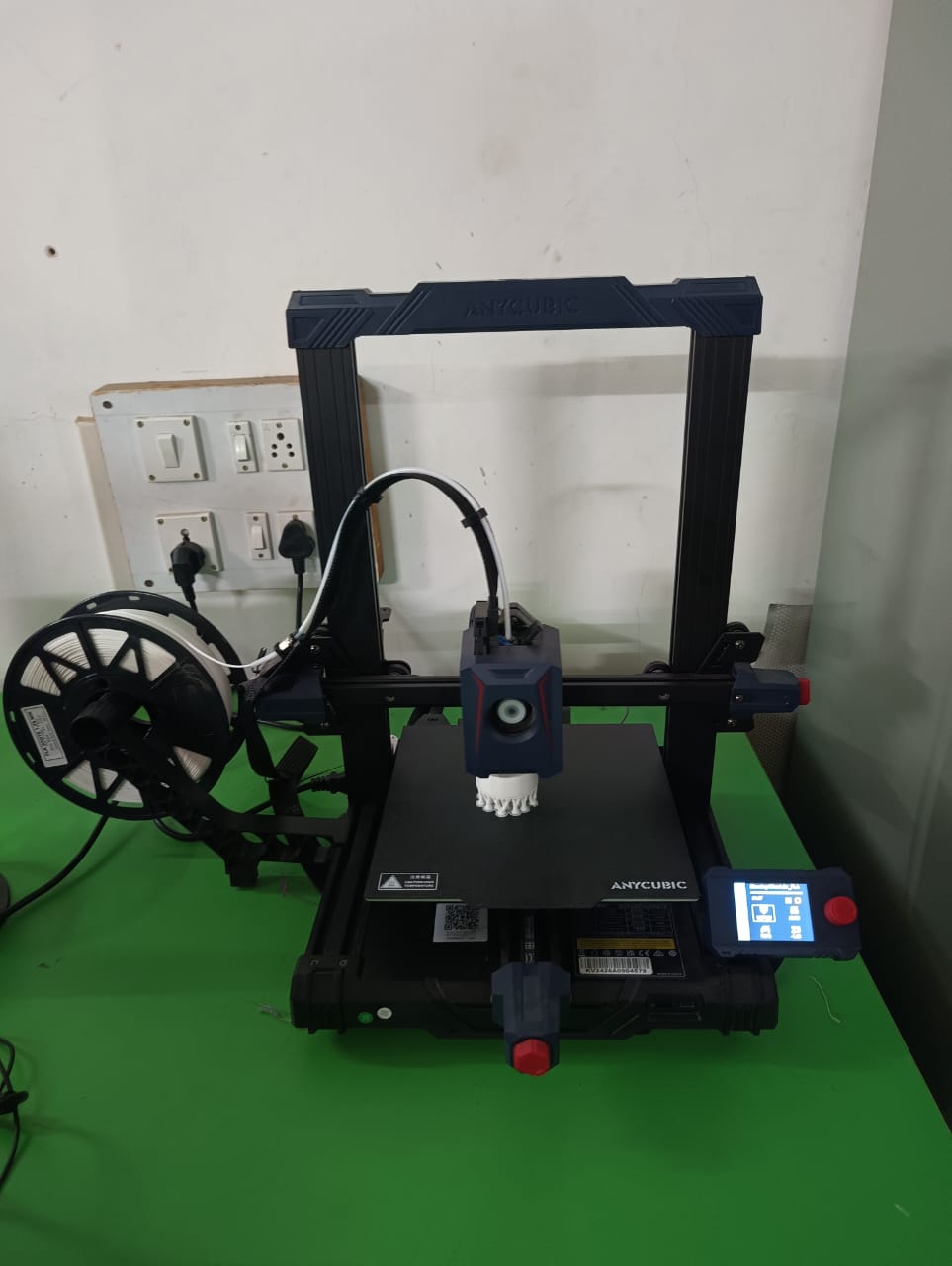
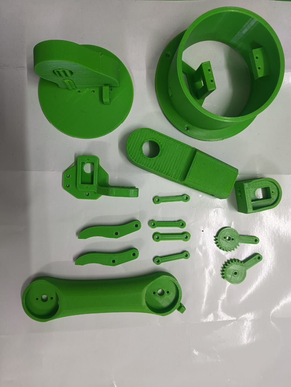
Finally, our part was successfully printed and ready for use.
PCB design
As I have successfully completed the manufacturing of the robotic arm components, the next step in my project is to move forward with the design of the custom PCB. I had already studied PCB design during the earlier weeks of the Fab Academy, which provided me with a clear understanding of the design workflow and essential considerations. Because of this prior experience, I find the process of designing the PCB relatively straightforward. I am now focusing on creating a compact and efficient circuit layout that will integrate all the required electronic components for my color sorting robot.
Design of PCB with KICAD software
As I explained in Week Six, I learned to use this software for PCB design. It is open-source and easily available online. Using this software, I designed a simple PCB for output devices.
The schematic diagram explains that I used the ESP32-C3 board for the PCB design. Additionally, I included an LED and connector. I designed a PCB for my project.
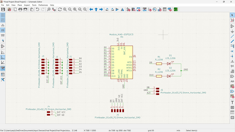
Then, I opened the PCB editor and used the "Route Track" command to make the necessary connections, ensuring that the PCB functions properly.
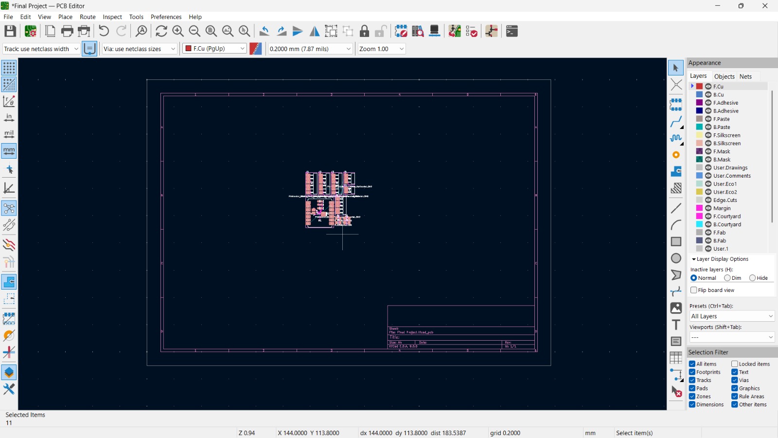
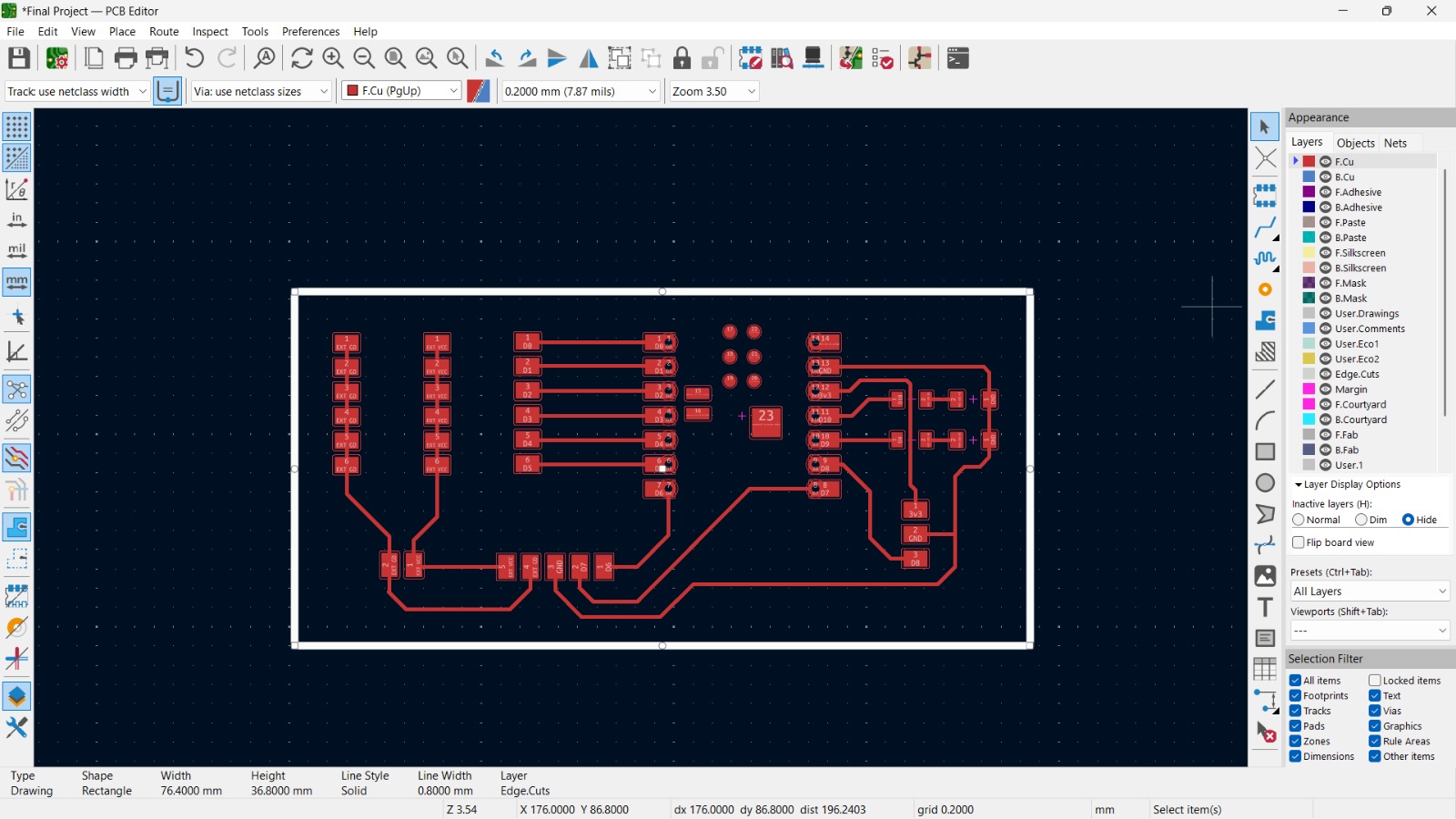
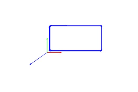
Then, using the Route Track command, I established proper connections on the PCB, ensuring a well-structured and functional circuit layout. Then, I used the Edge Cuts layer, selected the Draw Line tool, and created the PCB outline.
In the next step, the file needs to be saved for PCB fabrication. The files are saved in two ways: one for traces and another for the outline cut.
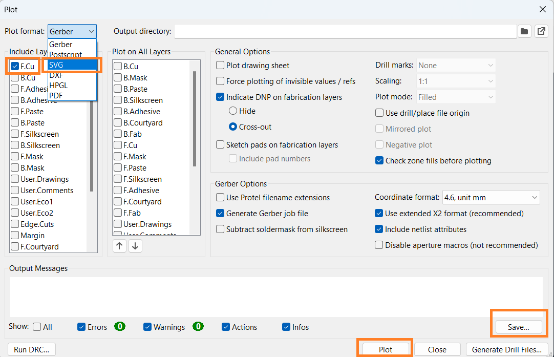
To save the file for traces:
1. Go to the File menu and select Plot.
2. In the Plot window, choose SVG as the output format.
3. Select F.Cu (the front copper layer).
4. The output message will display the save location of the file.
5. Finally, click Save to store the file.
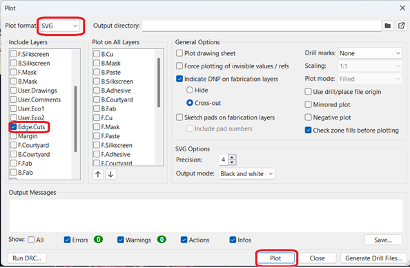
The same procedure is repeated for the edge cut, except instead of selecting F.Cu, choose Edge Cuts.
1. Go to the File menu and select Plot.
2. In the Plot window, choose SVG as the output format.
3. Select Edge Cuts instead of F.Cu.
4. Click Plot to generate the path for saving.
5. Finally, click Save to store the file.
All the aspects related to the schematic and PCB editors are not explained in detail here.
Generate Toolpath for PCB Milling
To generate the toolpath for CNC milling and create the PCB, I used the Mods Project online platform.
1. Open the Mods Project website.
2. Once the website loads, the main window appears.
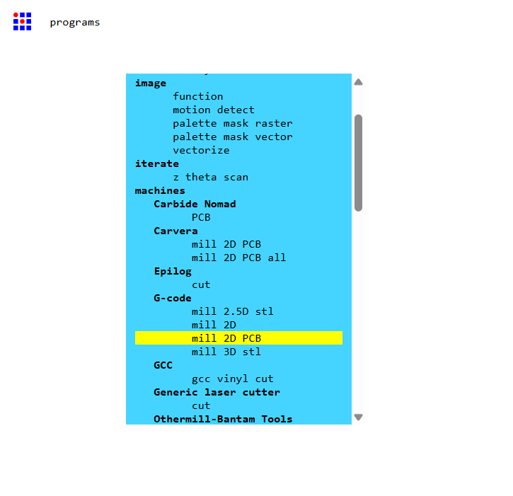
3. Then right click and from the available options, select program.

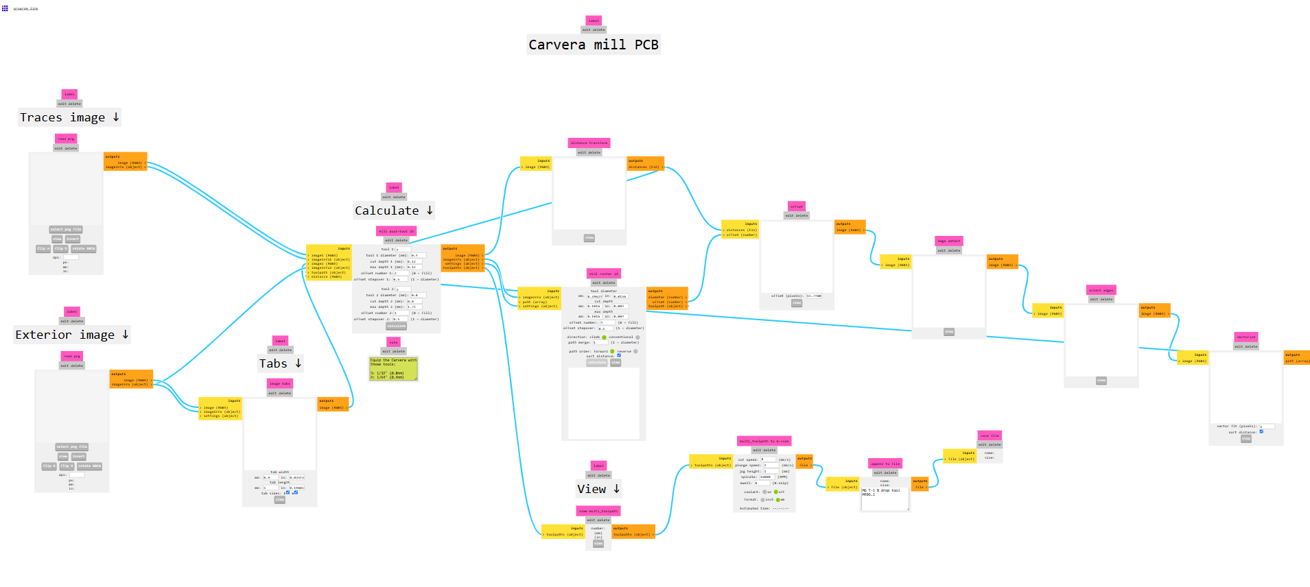
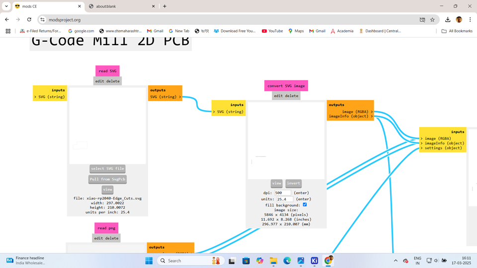
As the program opens, I scroll down and, under the G-code section, select Mill 2D PCB.
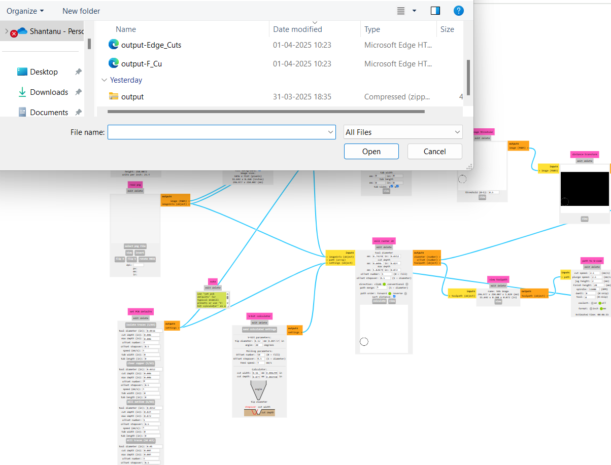
Then, go to Read SVG and select the SVG file. Then go to desired location and select .svg file format those are saved in KICAD software.
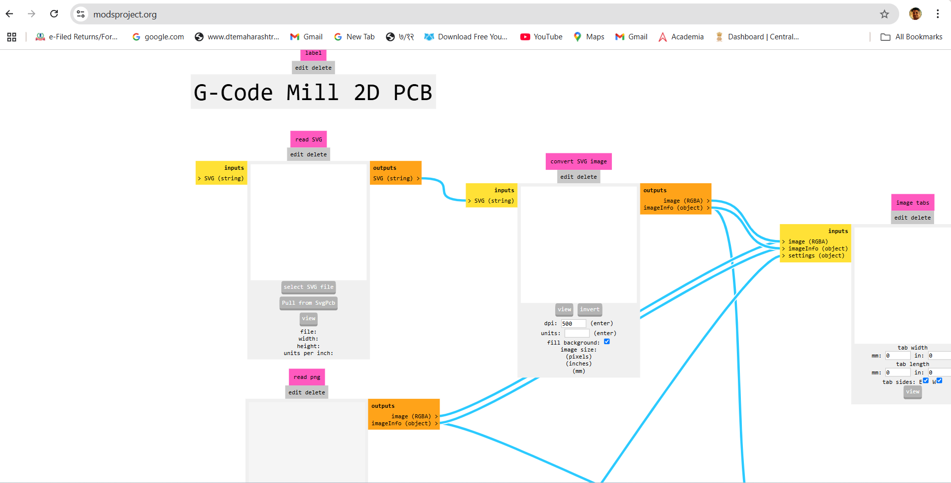
After selecting the file, press View to preview it.
Then, the preview appears in the Select SVG menu. Then, navigate to the "Convert SVG Image" section and select the "Invert" option.
Then, go to Set PCB Default and select Isolate Traces.

No changes are made in the Isolate Traces settings.
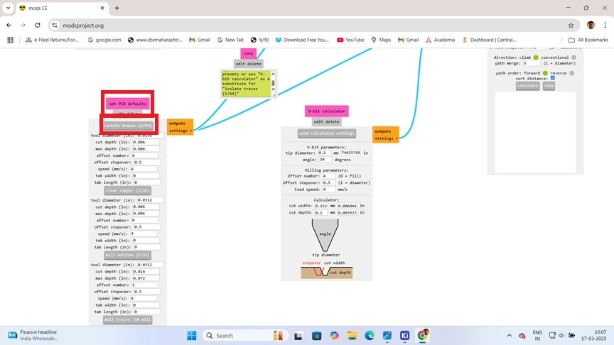
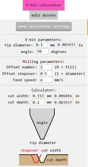
It looks like you're configuring the V-bit parameters for your CNC machining.
Open the V-bit Calculator in your software.
Set the parameters:
1. Tip Diameter: 0.1 mm
2. Angle: 30°
3. Cut Depth: 0.1 mm
4. Click on "Send Calculated Setting"
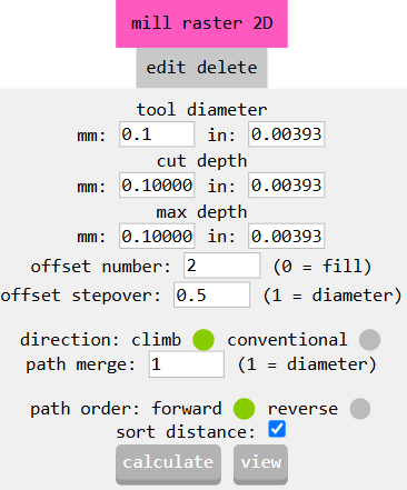
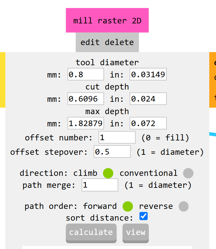
Then goes into mill raster 2d option. Change the Tool Diameter to 0.1 mm. Then, press the "Calculate" option. Once the calculation is complete, the file will be downloaded to the "Downloads" section.
Then click on the view option.
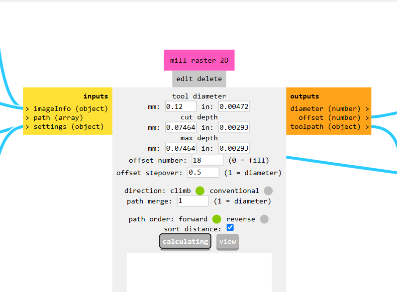
Click on the Calculate Button to generate the toolpath.The software will then generate the PCB milling file in .nc format.file is save in Downloads.Go to the "Downloads" folder and open the file. This file shows the toolpath.
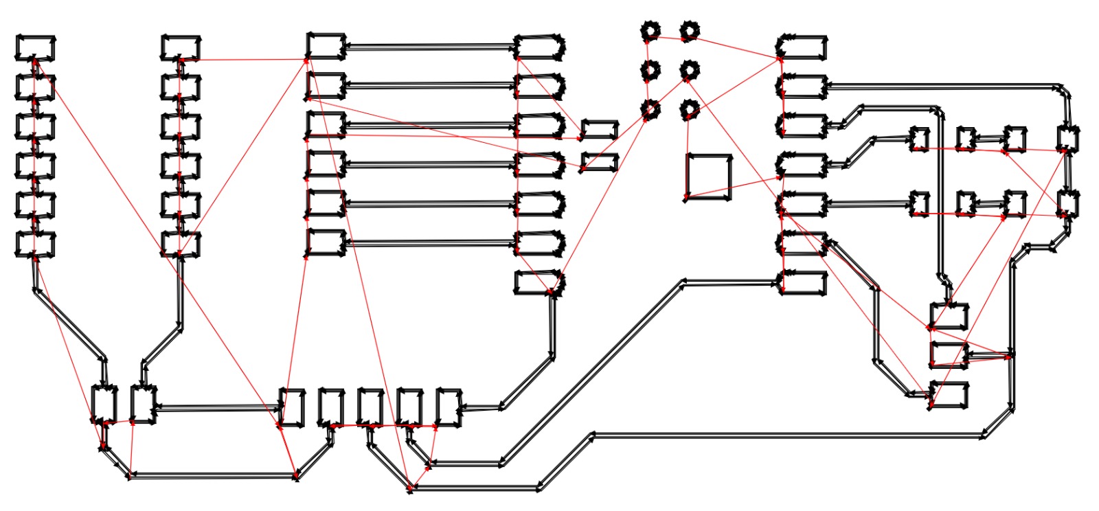
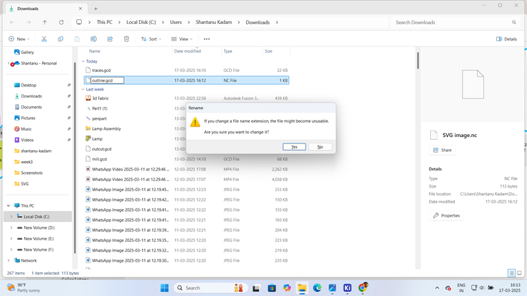
After that click on the calculate option it will generate the pcb milling file in . nc format.
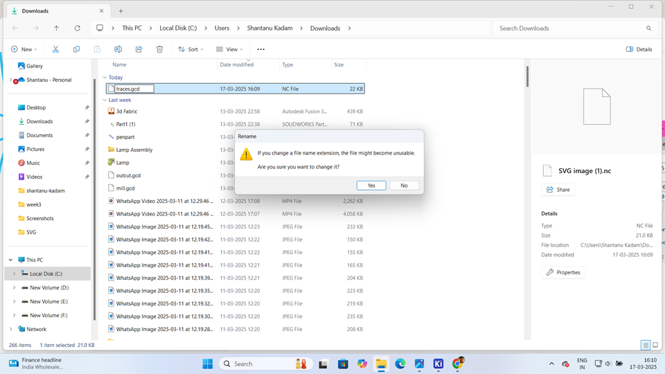
Navigate to the Downloads folder and locate the generated .nc file. Rename the file by changing its extension from .nc to .gcd.
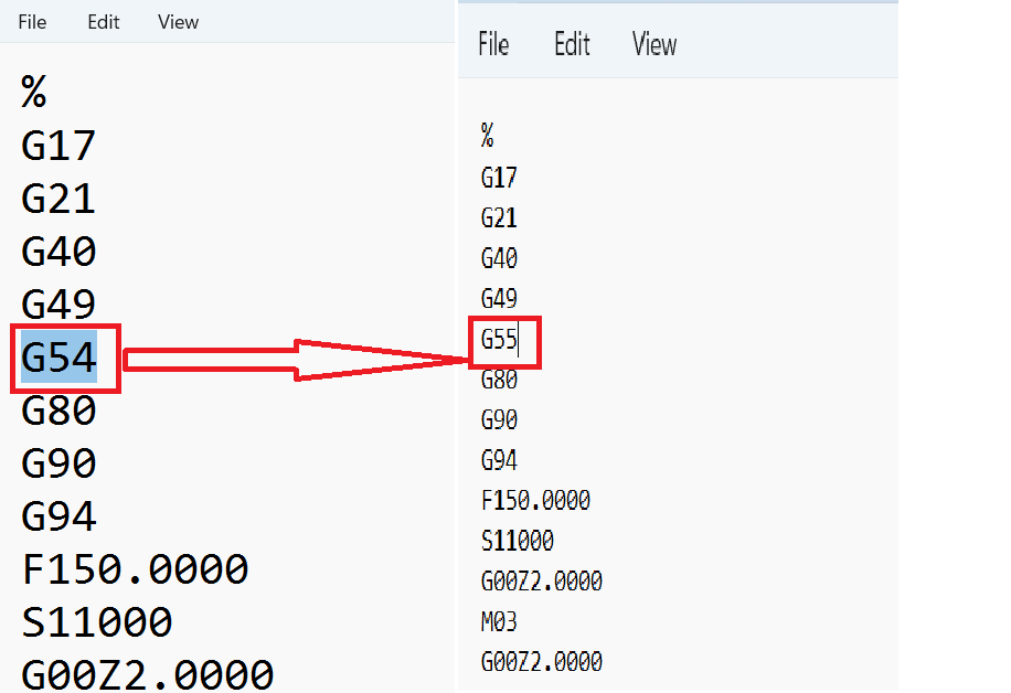
Once the file is saved in the .gcd format, open it using Notepad or a similar text editor. Locate the code G54 and replace it with G55 to adjust the work coordinate system for the PCB milling process. After making the modification, save the file and exit the editor.
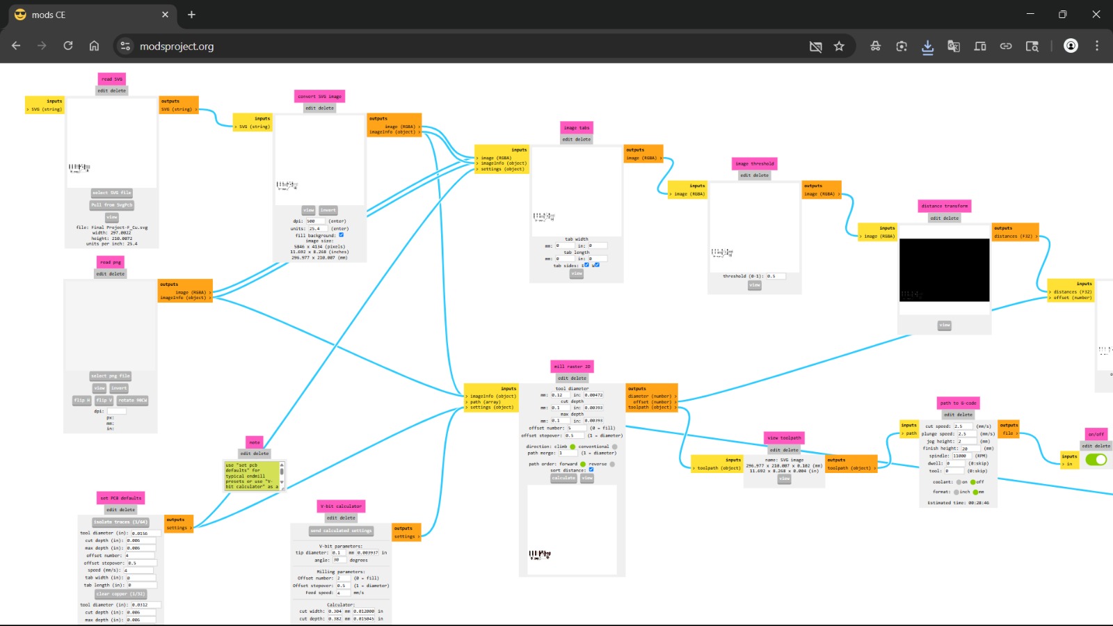
Next, access the Mods CE online software to generate the outline toolpath for the PCB milling process.
Then, go to Read SVG again, and in this menu, select the SVG file.
Then, go to Read SVG and select the SVG file. Then go to desired location and select .svg file format those are saved in KICAD software. Then select the edge_cut file and select open.
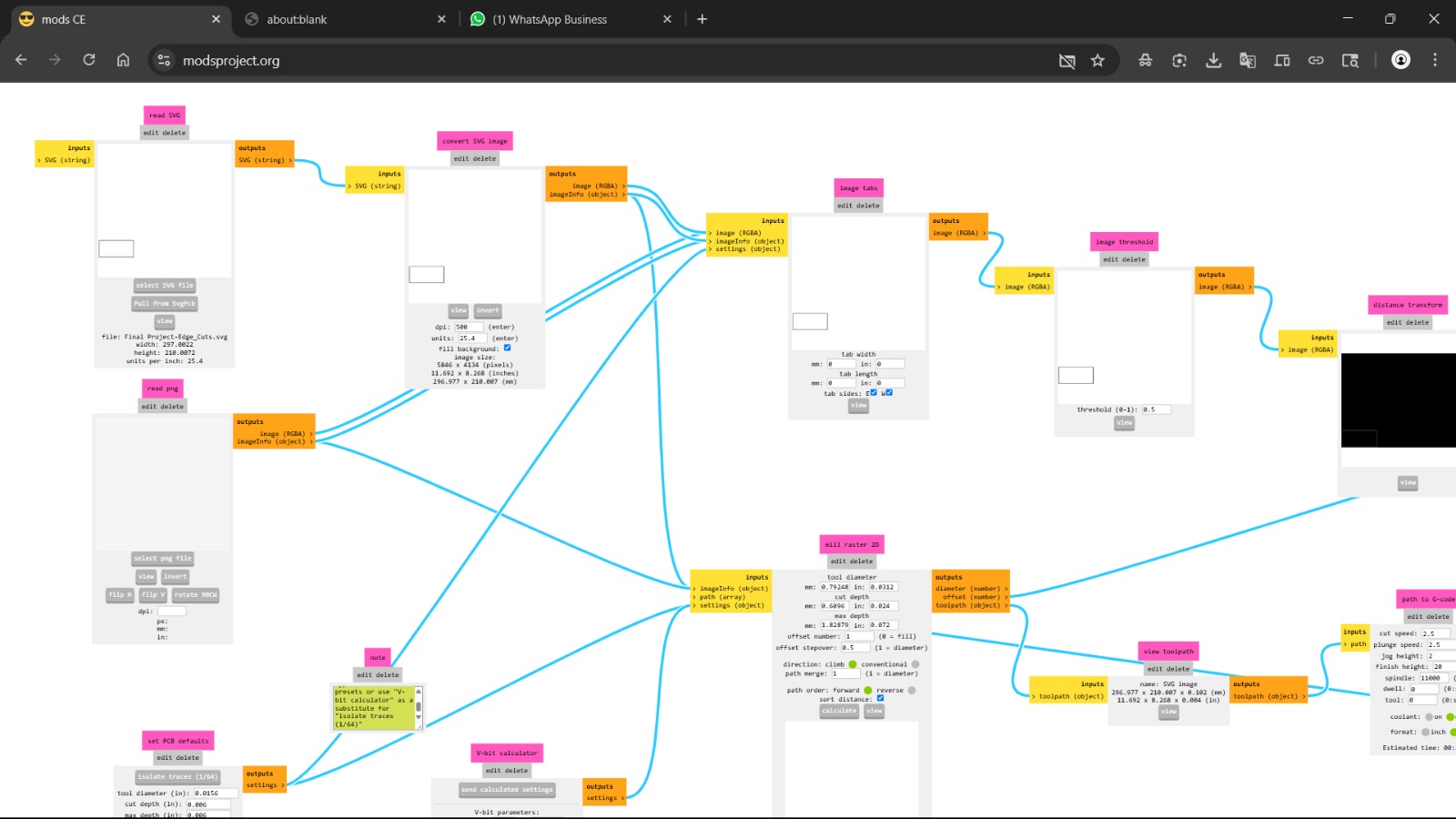
Then, go to Set PCB Default and select millout line (1/32).
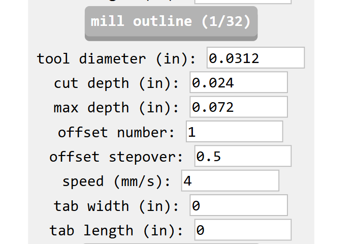
Without making any changes, go to Mill Raster 2D, change the tool diameter to 0.8mm, and save the changes.
After that click on the calculate option it will generate the pcb milling file in . nc format.
Navigate to the Downloads folder and locate the generated .nc file. Rename the file by changing its extension from .nc to .gcd.
Once the file is saved in the .gcd format, open it using Notepad or a similar text editor. Locate the code G54 and replace it with G55 to adjust the work coordinate system for the PCB milling process. After making the modification, save the file and exit the editor.
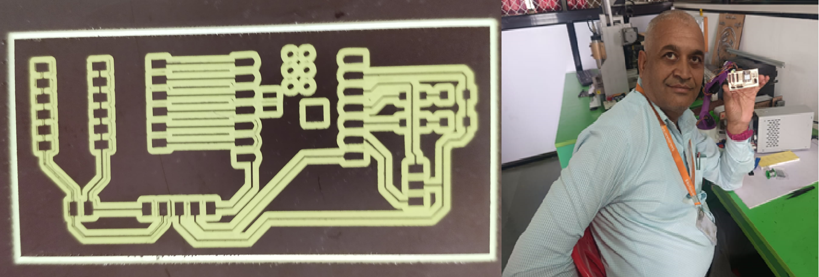
CNC Milling Process
Once the trace and outline files are generated, the PCB design is ready for manufacturing.
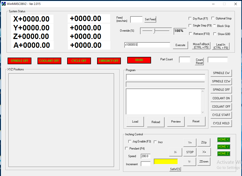
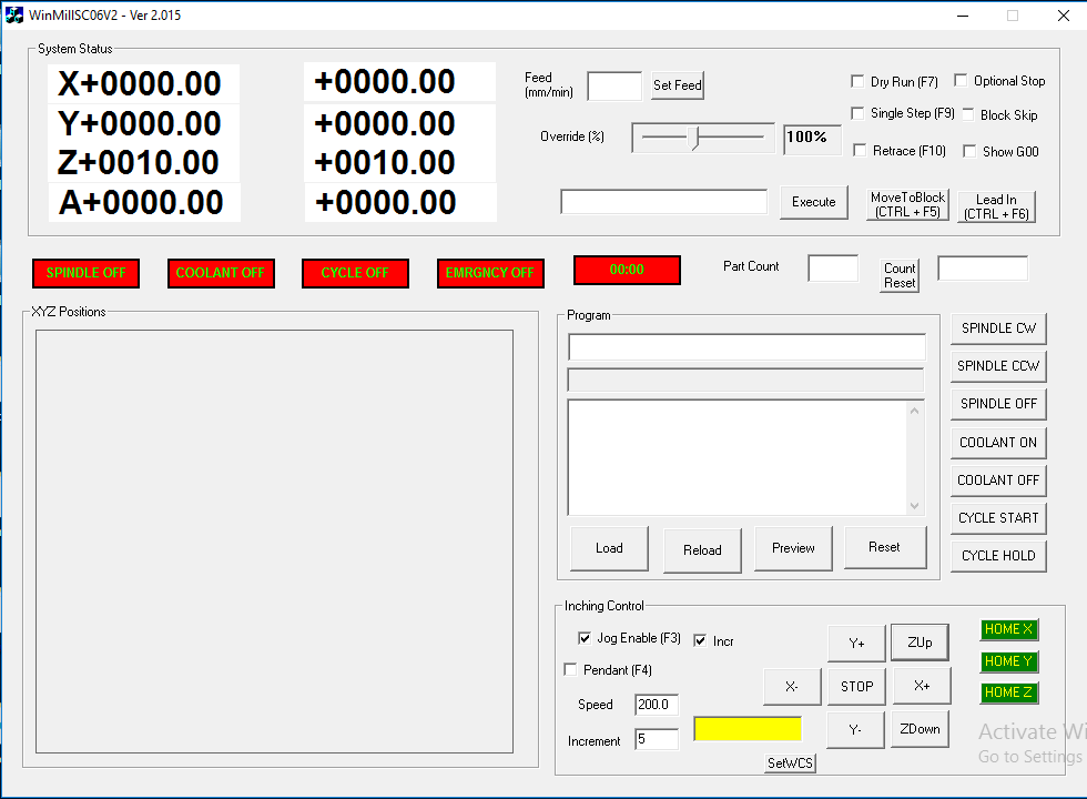
Then, proceed to the PCB milling machine, where the machine software is launched. Initially, the startup window is displayed.
Next, it is important to set the origin point. To do this, first, click on the "Jog Enable" menu, then select "Incremental." Set the desired increment value, and use the -X, +X, -Y, +Y, Z-up, and Z-down controls to position the spindle accurately.
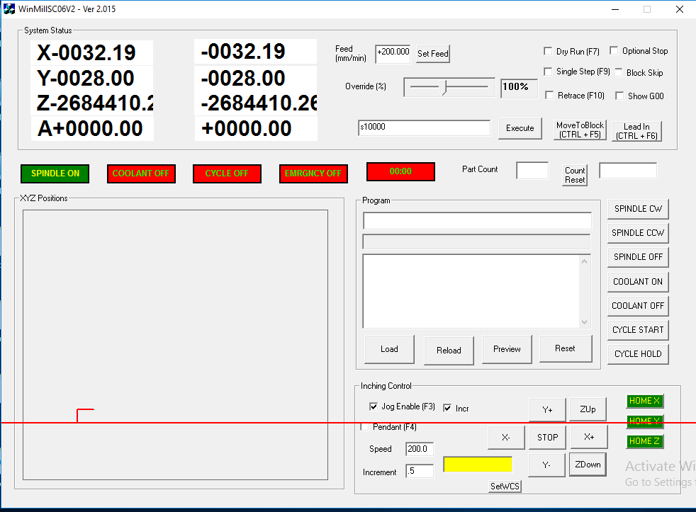
When go into the Set WCS menu and set X0, Y0, Z0, you are likely defining a new origin point for design.
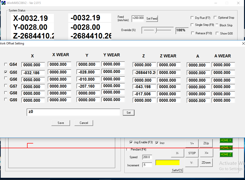
Then, click the Save button to set the origin for the PCB milling process. The screen will display the coordinates X0, Y0, Z0, confirming that the new reference point has been established.
Next, navigate to the Increments setting, configure it as needed, and click Z-Up to move the tool upward.
Then, navigate to the Load menu and select the program from the desired location.
Load the traces program to initiate the cutting process for the PCB traces.
Then, click Cycle Start to begin the milling process.
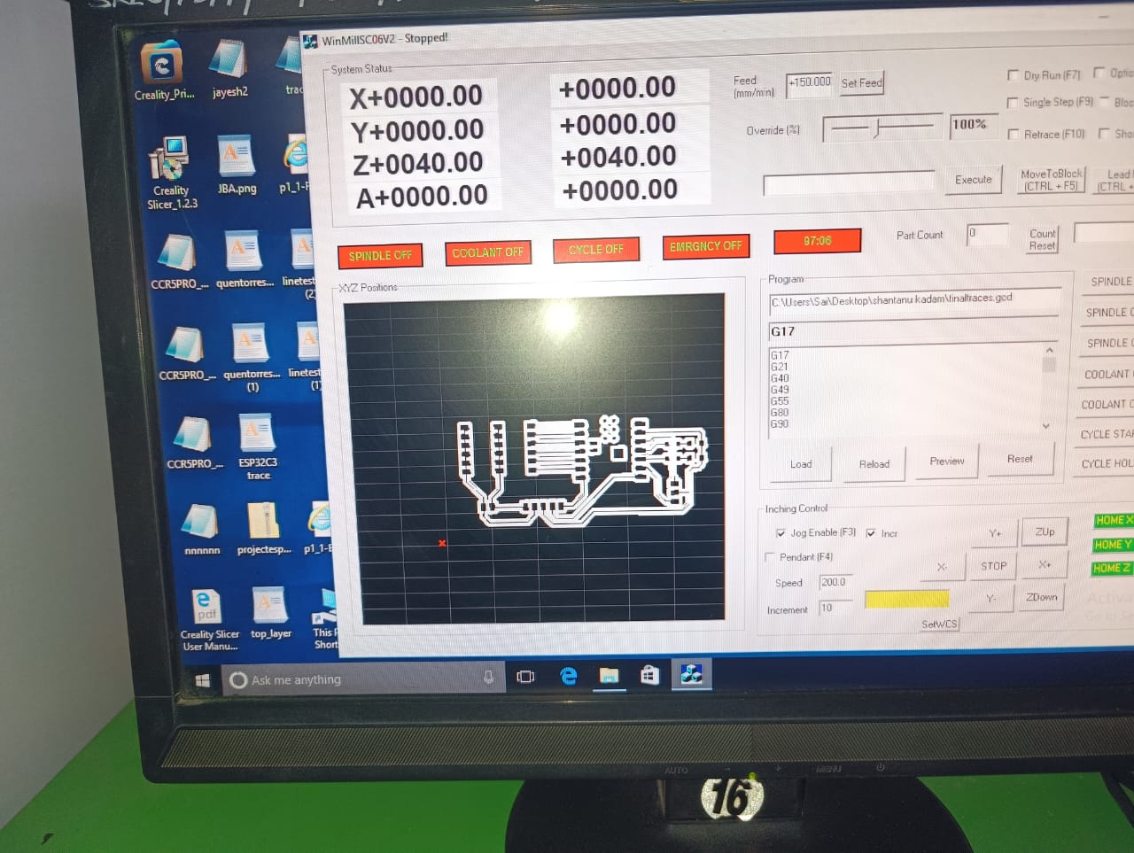
As the milling process begins, the tool rotates at a speed of 10,000 RPM, as specified in the program, and starts cutting the PCB traces.
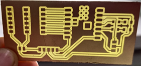
Once the traces are cut, the program is completed. Next, change the tool from a V-bit to a 0.8mm drilling tool. Then, following the same procedure, load the edge cut program while maintaining the previously set origin and click Cycle Start to begin the process.
Once the edge cut program cycle is completed, the PCB is ready for the soldering process.
PCB soldering
With the PCB milling process completed, the board is now ready for soldering. In the next step, the soldering process will be carried out.
In the soldering process, I connected the resistor, LED, connector, and ESP32-C3 board to the PCB.
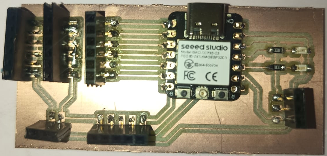
Hero Shot
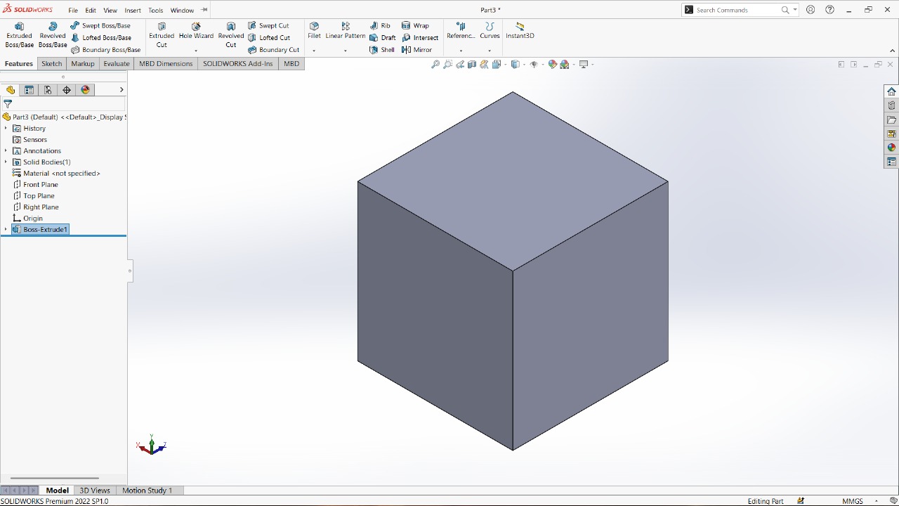
Design and Manufacturing of Block
1. Design of Block (1cm × 1cm × 1cm)
The design of the block was done using CAD (Computer-Aided Design) software, such as SolidWorks. A simple cube was created with the following dimensions:
Length: 1 cm
Width: 1 cm
Height: 1 cm
The design was saved in STL format, which is suitable for 3D printing. Care was taken to ensure proper orientation and minimal overhangs, which helps in efficient and accurate 3D printing.
2. Manufacturing of Block using 3D Printer
The prepared STL file was imported into slicing software like Ultimaker Cura, where the print settings were configured:
Material used: PLA (Polylactic Acid)
Layer height: 0.2 mm
Infill density: 20%
Print speed: 50 mm/s
Nozzle temperature: 200°C
Bed temperature: 60°C
After slicing, the G-code was generated and sent to the 3D printer. The printing process was monitored to ensure successful layer deposition. The final output was a precise 1cm cube, completed without any support material due to its simple geometry.
Design and Manufacturing of Conveyor
1. Design of Conveyor
The conveyor was designed using CAD (Computer-Aided Design) software, specifically SolidWorks. The key design steps included:
Creating 3D models of essential components such as:
1. Side frames
2. Roller mounts
3. Motor and bearing supports
4. Base plate and belt guides
Assembling all parts in the CAD environment to check fit and function.
Generating 2D profiles from the 3D model and exporting them in DXF format for laser cutting.
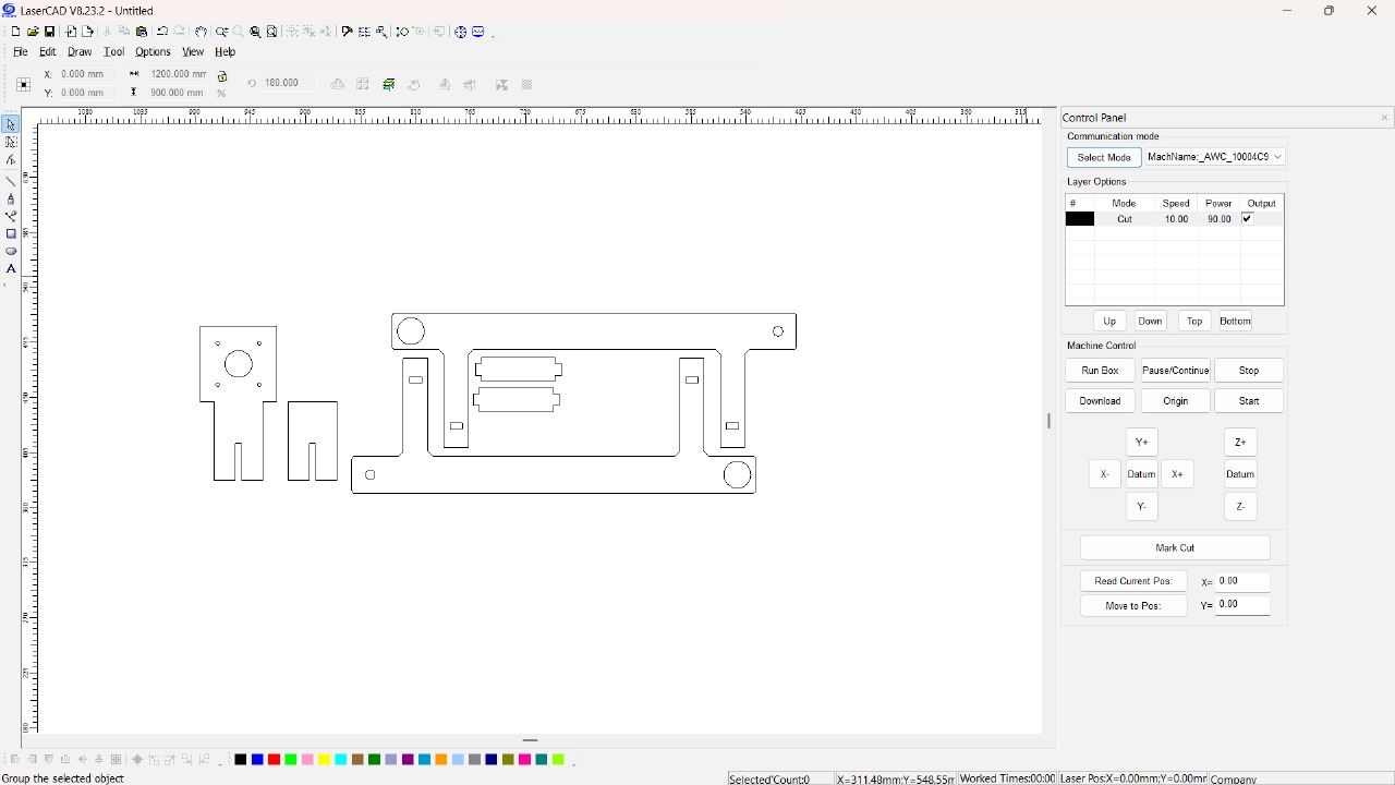
2. Manufacturing of Conveyor using Laser Cutting Machine (MDF Material)
The conveyor parts were fabricated using a laser cutting machine, and MDF (Medium Density Fiberboard) was selected as the material due to its:
Smooth surface
Easy machinability
Adequate strength for prototyping
Steps followed:
Imported the DXF files into laser cutting software.
Material: 4 mm MDF sheet
Configured laser parameters:
Cutting speed: Medium
Power: High (to cleanly cut through MDF)
Air assist: ON (to reduce burning)
Once cutting was complete, parts were carefully collected and sanded where needed.
The components were assembled using wood glue and screws (if necessary).
Motors, rollers, and the belt were installed.
Wiring was done and the conveyor was tested for smooth operation.
3. Roller Support: Design and Manufacturing
1. Design of Roller Support
The roller support was designed using CAD software SolidWorks to ensure proper fitment and function with the conveyor system. The design considerations included:
Dimensions: Designed based on the conveyor frame and roller shaft diameter.
Geometry: Cylindrical body with a central hole or shaft extension to fit motor or bearing housing.
Material: Intended to be printed in PLA, a lightweight and durable material suitable for prototype or light-duty use.
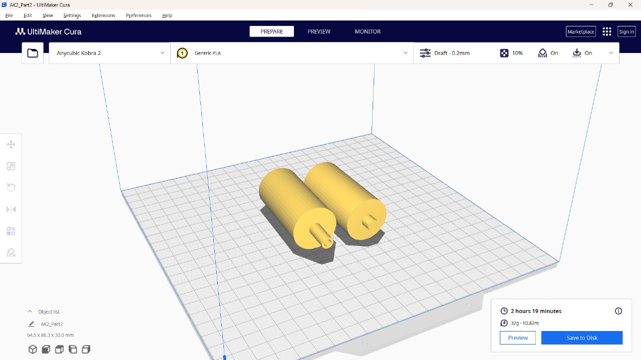
The model was exported as an STL file, then imported into Ultimaker Cura for slicing.
Print settings:
Layer height: 0.2 mm (Draft quality)
Material: Generic PLA
Estimated print time: 2 hours 19 minutes
Material usage: ~32g (10.82 meters of filament)
The Cura preview confirms the roller pair's dimensions (64.5 mm × 86.3 mm × 30 mm) and proper placement on the print bed.
2. Manufacturing of Roller Support using 3D Printing
The manufacturing was done using an Anycubic Kobra 2 3D printer. Steps:
Loaded G-code file generated from Cura onto the printer.
Ensured PLA filament was properly loaded and nozzle temperature was preheated.
Printing was initiated and monitored for consistent extrusion and layer bonding.
After ~2 hours, the printed roller supports were carefully removed from the bed.
Any minor supports or excess material were trimmed, and the parts were post-processed (light sanding if needed).
The final printed rollers matched the design and were ready to be mounted with shafts, bearings, or motor couplings in the conveyor system.
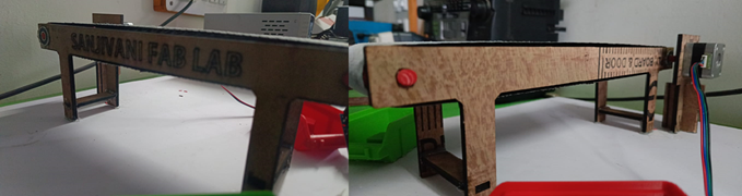
4. Assembling Process of Conveyor
The conveyor assembly involves integrating all the laser-cut and 3D-printed parts along with mechanical and electrical components to form a working system. The process was carried out in a stepwise manner:
Step 1: Preparation of Components
All MDF laser-cut parts were collected and cleaned.
3D printed roller supports and rollers were removed from the print bed and trimmed for a clean finish.
Required tools and hardware like screws, nuts, spacers, bearings, pulleys, and motors were gathered.
Step 2: Assembly of Conveyor Frame
The side panels and base plate were first fixed together using wood glue and screws to form the rigid frame.
Support brackets and motor mount plates were then attached at the specified locations as per the CAD design.
Step 3: Installation of Rollers
Bearings were inserted into the ends of the 3D-printed rollers (if bearing slots were included).
The rollers were placed into the roller support mounts, which were fixed to the frame.
Shafts or axles were passed through the rollers to ensure free and smooth rotation.
Step 4: Mounting the Motor and Pulley
A DC gear motor or stepper motor was mounted on the motor support plate.
A pulley was fixed onto the motor shaft and aligned with the roller pulley.
A rubber belt or timing belt was looped over the motor and roller pulleys for transmission.
Step 5: Belt Installation
A conveyor belt (PVC) or flexible strip was placed over the rollers.
Belt tension was adjusted by loosening/tightening the roller mounting points or using a tension adjustment mechanism.
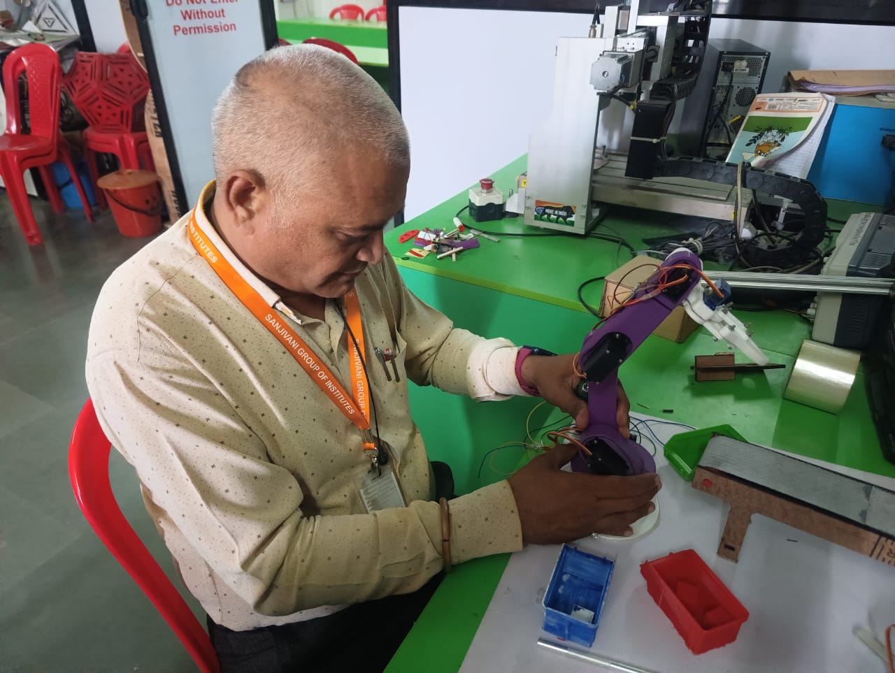
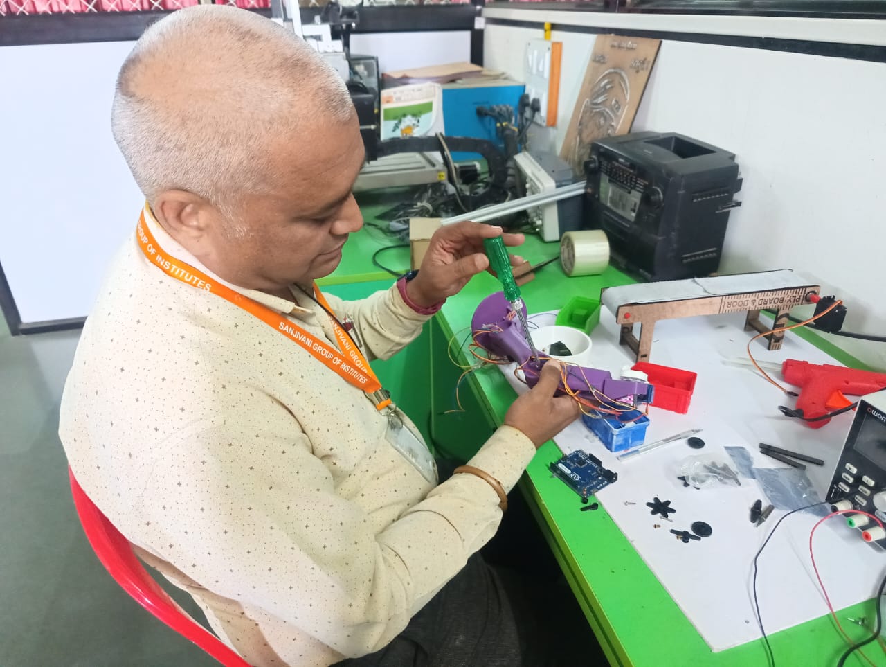
Assembling a 3D-Printed Robotic Arm
The robotic arm consists of multiple 3D-printed components including base, joints, arms, gears, and linkages. The following step-by-step process was used for its assembly:
Step 1: Organize All Components
Lay out all 3D-printed parts on a clean surface.
Identify and group the components:
Base & Mounting Bracket
Upper and Lower Arm Segments
Rotational Joints & Gears
Gripper Components
Linkage Arms & Connectors
Step 2: Assemble the Base and Rotating Platform
Attach the rotating platform onto the circular base support using screws or bearings as per the design.
Ensure smooth rotation; insert a bearing or washer if needed for stability.
Step 3: Fix the First Arm Segment
Connect the first (lower) arm to the rotating base using a pivot joint.
Secure the joint using screws or bolts, ensuring it can rotate freely (typically driven by a servo motor or gear).
Step 4: Attach the Second Arm Segment
Connect the second (upper) arm to the end of the lower arm using a rotating joint mechanism.
Insert screws or pins through the provided holes and fasten.
Step 5: Assemble and Attach Gear Mechanism
Insert the spur gears into the slots provided near joints (for motion transfer).
Ensure meshing is proper so that motion from one part drives the next.
Add motor shafts or servo horns if gears are motor-driven.
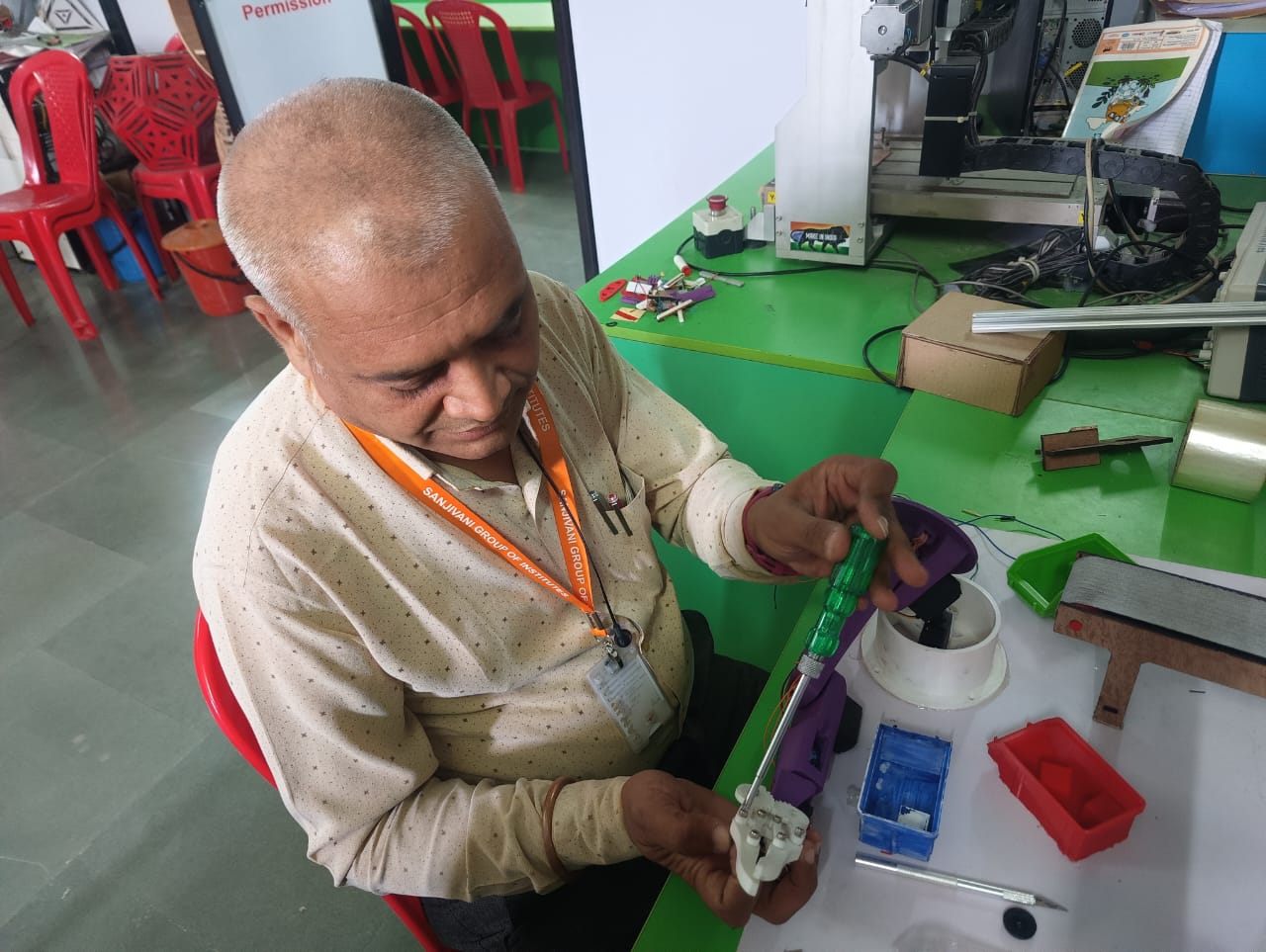
Step 6: Mount the Gripper (End Effector)
Assemble the gripper parts and mount them on the top end of the upper arm.
Fix the linkage arms that control gripper opening and closing.
Use a small servo motor or spring mechanism if applicable.
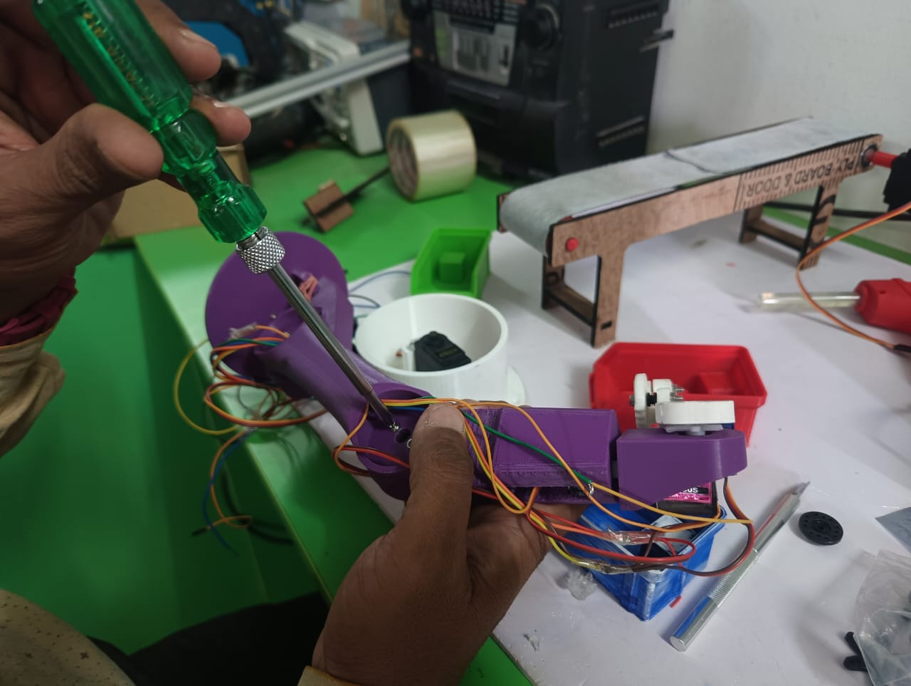
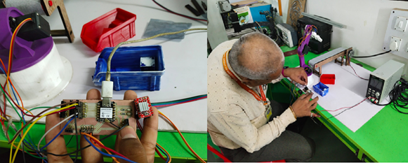
Electrical Wire Connections
Power Supply:
Servo motors are powered using an external regulated power supply
Microcontroller Interface:
Each servo motor’s signal wire (usually orange or white) is connected to a PWM-enabled pin on the microcontroller.
The VCC wire is connected to the 5V supply.
The GND wire is connected to the common ground of the microcontroller and power supply.
Programming for Color Sorting Robot
1. Arduino IDE Programming (Microcontroller Side)
The microcontroller used in this project is the XIAO ESP32-C3, programmed using the Arduino IDE. It controls:
The servo motors for sorting
The DC motor for the conveyor belt
Communication with the host system (PC with OpenCV)
Key Features of the Program:
Waits for color detection input (from OpenCV).
Based on the input (R, G, B), moves the respective servo.
Controls the conveyor belt motor using digital/analog pins.
2. Arduino Code (Servo + Motor Control):
#include < Servo.h >
Servo servo1, servo2, servo3, servo4, servo5, servo6;
void setup() {
Serial.begin(9600); // Initialize serial communication
Serial.println("System Initialized. Waiting for color input (1=Red, 2=Green, 3=Blue)...");
attachAllServos();
Serial.println("Moving to Home Position...");
moveToHome();
detachAllServos();
Serial.println("Servos detached. Ready for next operation.");
}
void loop() {
if (Serial.available() > 0) {
int colorInput = Serial.parseInt();
Serial.print("Received color code: ");
Serial.println(colorInput);
attachAllServos();
Serial.println("Moving to Home Position...");
moveToHome();
if (colorInput == 1) {
Serial.println("Picking object for RED...");
pickFromConveyor();
Serial.println("Placing object to RED drop zone...");
placeRed();
} else if (colorInput == 2) {
Serial.println("Picking object for GREEN...");
pickFromConveyor();
Serial.println("Placing object to GREEN drop zone...");
placeGreen();
} else if (colorInput == 3) {
Serial.println("Picking object for BLUE...");
pickFromConveyor();
Serial.println("Placing object to BLUE drop zone...");
placeBlue();
} else {
Serial.println("Invalid input received.");
}
Serial.println("Returning to Home Position...");
moveToHome();
detachAllServos();
Serial.println("Cycle Complete. Awaiting next input...");
}
}
// --------- Functions -----------
void attachAllServos() {
servo1.attach(3);
servo2.attach(5);
servo3.attach(6);
servo4.attach(9);
servo5.attach(10);
servo6.attach(11);
Serial.println("All servos attached.");
}
void detachAllServos() {
servo1.detach();
servo2.detach();
servo3.detach();
servo4.detach();
servo5.detach();
servo6.detach();
Serial.println("All servos detached.");
}
void moveToHome() {
servo1.write(120);
servo2.write(120);
servo3.write(160);
servo4.write(90);
servo5.write(60);
servo6.write(40);
delay(1000);
Serial.println("Moved to Home Position.");
}
void pickFromConveyor() {
servo1.write(120);
servo2.write(120);
servo3.write(130);
servo4.write(90);
servo5.write(60);
delay(1000);
servo6.write(0); // Close gripper
delay(1000);
Serial.println("Picked object from conveyor.");
}
void placeRed() {
servo3.write(160);
delay(1000);
servo1.write(60);
delay(1000);
servo3.write(130);
delay(1000);
servo6.write(40); // Open gripper
delay(1000);
servo3.write(160);
delay(1000);
Serial.println("Placed RED object.");
}
void placeGreen() {
servo3.write(160);
delay(1000);
servo1.write(0);
delay(1000);
servo3.write(130);
delay(1000);
servo6.write(40); // Open gripper
delay(1000);
servo3.write(160);
delay(1000);
Serial.println("Placed GREEN object.");
}
void placeBlue() {
servo3.write(160);
delay(1000);
servo1.write(180);
delay(1000);
servo3.write(130);
delay(1000);
servo6.write(40); // Open gripper
delay(1000);
servo3.write(160);
delay(1000);
Serial.println("Placed BLUE object.");
}
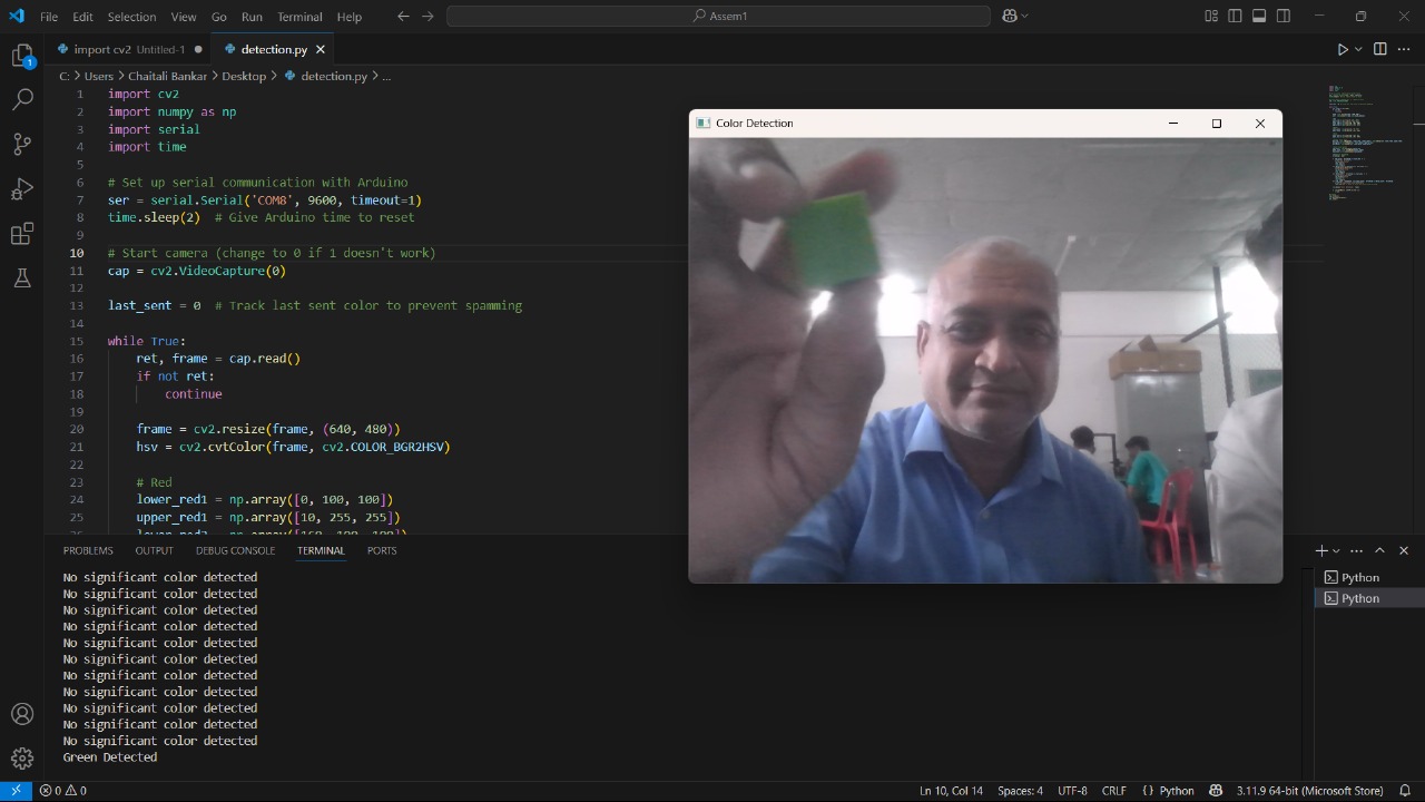
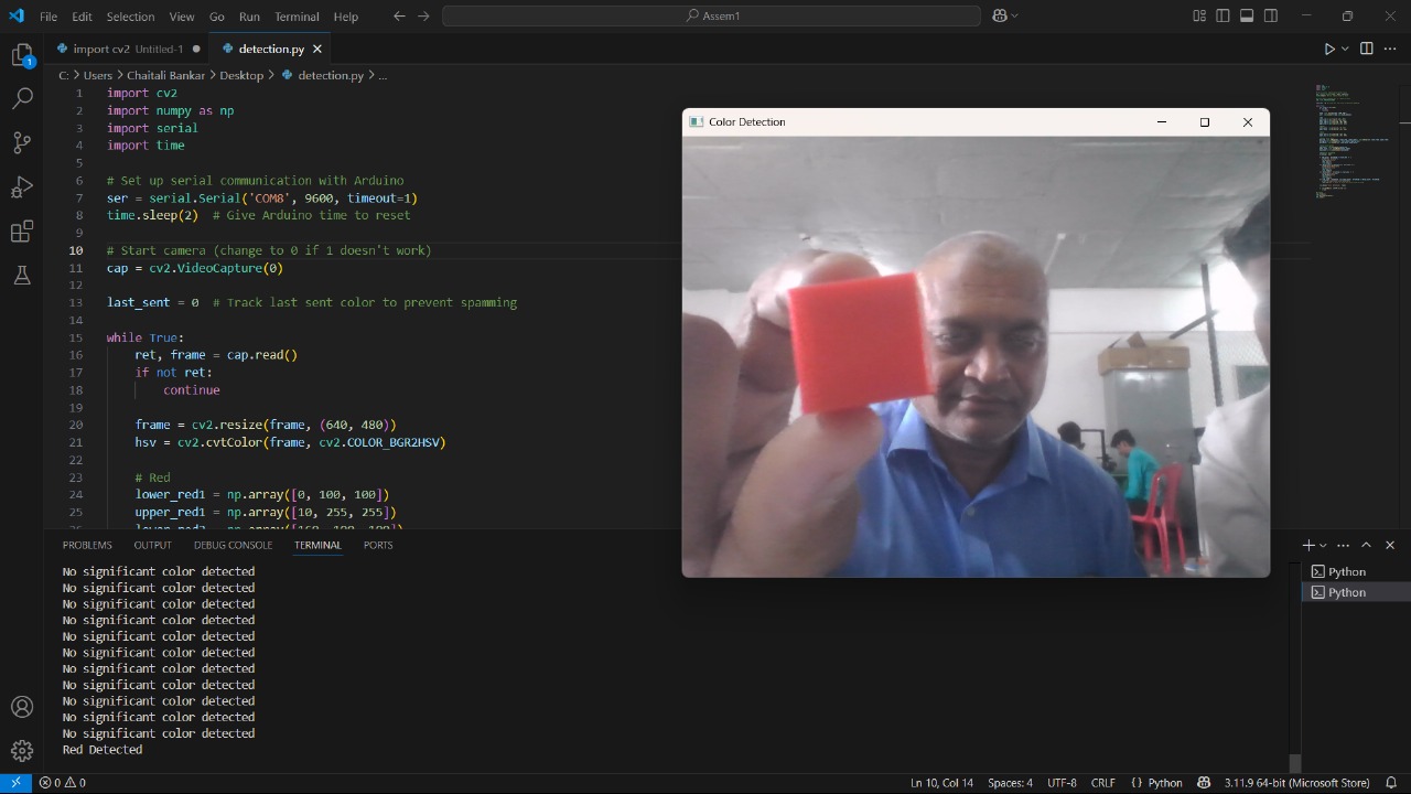
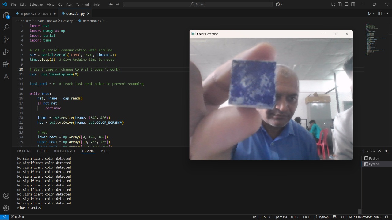
3. OpenCV Programming (Color Detection on PC)
The color sensor is implemented using a webcam and processed in real-time using Python with OpenCV.
Key Features of the Program:
Captures live video from webcam.
Detects object color (Red, Green, or Blue) in the region of interest (ROI).
Sends corresponding character (R, G, B) via serial to ESP32-C3.
4. Python OpenCV Code:
import cv2
import numpy as np
import serial
import time
# Set up serial communication with Arduino
ser = serial.Serial('COM8', 9600, timeout=1)
time.sleep(2) # Give Arduino time to reset
# Start camera (change to 0 if 1 doesn't work)
cap = cv2.VideoCapture(0)
last_sent = 0 # Track last sent color to prevent spamming
while True:
ret, frame = cap.read()
if not ret:
continue
frame = cv2.resize(frame, (640, 480))
hsv = cv2.cvtColor(frame, cv2.COLOR_BGR2HSV)
# Red
lower_red1 = np.array([0, 100, 100])
upper_red1 = np.array([10, 255, 255])
lower_red2 = np.array([160, 100, 100])
upper_red2 = np.array([179, 255, 255])
# Green
lower_green = np.array([40, 70, 70])
upper_green = np.array([80, 255, 255])
# Blue
lower_blue = np.array([100, 150, 0])
upper_blue = np.array([140, 255, 255])
# Create color masks
mask_red = cv2.inRange(hsv, lower_red1, upper_red1) + cv2.inRange(hsv, lower_red2, upper_red2)
mask_green = cv2.inRange(hsv, lower_green, upper_green)
mask_blue = cv2.inRange(hsv, lower_blue, upper_blue)
# Count color pixels
red_count = cv2.countNonZero(mask_red)
green_count = cv2.countNonZero(mask_green)
blue_count = cv2.countNonZero(mask_blue)
# Detection threshold
threshold = 2000
if red_count > threshold and last_sent != 1:
print("Red Detected")
ser.write(b'1\n')
last_sent = 1
time.sleep(2)
elif green_count > threshold and last_sent != 2:
print("Green Detected")
ser.write(b'2\n')
last_sent = 2
time.sleep(2)
elif blue_count > threshold and last_sent != 3:
print("Blue Detected")
ser.write(b'3\n')
last_sent = 3
time.sleep(2)
elif red_count < threshold and green_count < threshold and blue_count < threshold:
print("No significant color detected")
last_sent = 0 # Reset to allow next valid color to send
cv2.imshow("Color Detection", frame)
if cv2.waitKey(1) & 0xFF == ord('q'):
break
# Cleanup
cap.release()
cv2.destroyAllWindows()
ser.close()
Project Completed
I am happy to share that I have successfully completed my entire project along with the project video. The Colour Sorting Robot is now fully functional, and the video documentation is ready for presentation and submission.